Have questions? Need Help?
757.723.6531 | 800.950.2468

Teledyne Hastings Instruments Blog

Fittings for Mass Flow and Vacuum Instruments

Posted by Doug Baker on Mon, Jun 20, 2022 @ 02:48 PM

Choosing Your Fittings_Blog Social Media ImageIn this blog, we will discuss various system connections, or fittings, that are available for both our mass flow and vacuum products. We will briefly explore why you might select a particular family of fittings for your system. Also, we will touch on some basic installation Dos and Don’ts.


Mass Flow Meters and Mass Flow Controllers

Many users of low flow (0-5 sccm up to 0-25 slm) instruments appreciate the convenience of compression fittings. The Swagelok ™ brand of compression fittings is very popular, and many users ask for these by name. Compression fittings can be very reliable; also, they can be quickly uninstalled and reinstalled as needed. And, unlike VCR ™ and VCO ™ fittings (we will talk more about these in a minute), compression fittings do not require a separate o-ring or single-use gasket. Our flow products are offered with various size Swagelok™ brand compression fittings. While the 1/4” size is the most popular for many low flow applications, we also offer, even smaller, 1/8” size as well. Metric sizes, including 10 mm and 12 mm, are also available. Then, for even higher flow applications, we also offer 1/2”, 3/4”, 1”, 1.5” and even 2” Swagelok ™ fittings. Note that the largest compression fittings require a swaging tool. (Link?)

Per the “Tube Fitter’s Manual” published by Swagelok®, here are the steps for manual installation of Swagelok Tube Fittings up to 1 in. or 25 mm.

  1. Fully insert the tube into the fitting and against the shoulder; rotate the nut finger tight.

    Swagelok Tube Fitting - insert tube into fitting
  2. Mark the nut at the 6 o’clock position.

    Swagelok Tube Fitting - mark nut at 6 oclock

  3. While holding the fitting body steady, tighten the nut 1 ¼ turns to the 9 o’clock position.
    For 1/16, 1/8, and 3/16 in. or 2, 3, and 4 mm tube fittings, tighten the nut ¾ turn to the 3 o’clock position.

    Swagelok Tube Fitting - tighten nut

Reassembly Procedure is as follows:

  1. Prior to disassembly, mark the tubing at the back of the nut, mark a line along the nut and body flats. Use these marks to ensure that you return the nut to the previously pulled-up position.

    Swagelok Tube Fitting - mark tubing
  2. Insert the tubing or tube adapter end connection with pre-swaged ferrules into the fitting until the front ferrule seats against the fitting body.

    Swagelok Tube Fitting - insert tubing
  3. While holding the fitting body steady, rotate the nut with a wrench to the previously pulled-up position, as indicated by the marks on the tubing and flats. At this point, you will feel a significant increase in resistance. Tighten the nut slightly.

    Swagelok Tube Fitting - rotate nut

The VCR ™ system from Swagelok™ is very popular with users who need high purity, all-metal, reliable sealing for either positive pressure or vacuum applications. For these fittings, a gasket, usually metal, is used to seal between the two symmetric sealing faces. In some cases, an elastomeric or PTFE gasket can be used. Metal gaskets (e.g. copper, nickel, or stainless steel) in VCR ™ connections should only be used once. Metal gaskets can be purchased with a retainer to hold the gasket in place when installing. The gasket is secured between the mating surfaces and the nut is drawn finger tight. Then, to finish installation, two wrenches are used to tighten the connection and create the leak-free seal. Note that copper gaskets require a 1/4 turn (90°) beyond finger tight while nickel and stainless steel only require an 1/8 (45°) of a turn.

HFC-302 with VCR fittingHFC-302 with VCR fittings


Live chat

The VCO™ system is convenient when the user wants to have fast make and break connections. It is also handy when space is limited. One part of the VCO™ connection includes an o-ring while the mating connection has a flat smooth finish. Installation is easy. A nut is made finger tight and then a wrench is used to tighten by 1/8 (45°) of a turn.

Usually, your fitting selection and piping are going to be a function of the flow rate. Our application engineers are available via email, phone or LiveChat to help you.


Vacuum Gauges

There are several popular systems of connections for vacuum gauges. Selection of a system should be driven by base pressure, outgassing load, and of course, cost.

For many users who just need to reach the mTorr range of pressures, tapered pipe thread (NPT: National Pipe Tapered) connections are simple, require no external clamps or bolts, and can be assembled quickly. However, PTFE tape or some other sealant should be used on the threads for two reasons. First, the tape/sealant fills the void between the mating thread surfaces and second, the tape/sealant acts as an anti-galling lubricant between the threads.

When wrapping PTFE tape onto NPT threads, start with clean surfaces and a clean cut of the tape. Make sure the tape is flat as it is wound onto the sealing surfaces and wrap in the direction of the threads. Two to three wraps is adequate. End the wrap with a clean cut of the tape. Tighten the connection with a wrench. How tight? Well, there is no right answer except to say that you want the system to seal, but you don’t want the threads to strip. So, use a wrench until tight, but do not try to force and overtighten.

The KF system is convenient for users who need a fast leak tight system connection for their vacuum gauges. “KF” is short for Klein Flansche which is German for small flanges. Vacuum systems with KF flanges can reach into the 10-8 Torr range. KF sizes, such as KF-16 and KF-25, are related to the maximum nominal inner diameter tubing in millimeters that can be attached to the flange.

DV-6-KF-16Teledyne DV-6-KF-16 (Shown with o-ring assembly and clamp)


And lastly, ConFlat hardware is ideal for high vacuum and ultrahigh vacuum systems. ConFlat flanges have a knife-edge that seals against a gasket, usually copper. The connection is made by tightening a series of bolts; the number of bolts is a function of the size of the flange. Clean, baked, suitably pumped systems using ConFlat hardware have been known to reach pressures below 10-13 Torr.

DV-6 Gauge Tube with ConFlat FlangeDV-6 Gauge Tube with ConFlat Flange


If you would like to discuss your application for vacuum gauges, mass flow meters, or mass flow controllers, we are standing by. You can reach us by phone (1-800-950-2468), email (hastings_instruments@teledyne.com) , or by using our LiveChat box at www.teledyne-hi.com or clicking on the box below.

CONTACT US FOR MORE INFORMATION

Note: All photos of Swagelok fittings in this blog are used with their written permission.

Tags: mass flow controller, mass flow meter, mass flow instruments

Argon gas (Ar) Applications – Accurate Vacuum Measurement and Flow Control

Posted by Doug Baker on Mon, Mar 28, 2022 @ 11:30 AM

Argon Gas Applications_Blog Social Media ImageThis blog is the next installment in a series focusing on industrial gases. The first blog featured SF6 and can be found here:   http://info.teledyne-hi.com/blog/sulfur-hexafluoride-gas-sf6 . The second blog focused on carbon dioxide (CO2): https://info.teledyne-hi.com/blog/carbon-dioxide-co2 . Now we will take a look at Argon.

Argon (Ar) makes up just under 1% (0.93%) of the composition of air. Argon is odorless, tasteless, and has no color. It is a member of the noble gases. Science Notes (sciencenotes.org ) gives an interesting history of the term, “Noble gas”:

The term “noble gas” comes from a translation of the German word Edelgas, which means noble gas. German chemist Hugo Erdmann coined the phrase in 1898. Like a nobleman might consider it undignified to associate with commoners, noble gases tend not to react with other elements.

In any case, noble gases such as Argon are found in the right-hand column of the periodic table which means they have completed valence shells. The noble gases are generally monatomic and are mostly inert. The word “argon” comes from the Greek word “argos” which, according to Webster’s dictionary, means “idle, lazy.” This definition makes sense because Argon gas is quite unreactive and rarely forms compounds.

Because of its inert behavior, Argon gas has many uses. One of the most popular is the use of Argon as a cover gas when welding. A flow of Argon can provide an inert environment which prevents oxidation of welds and also allows the welder to have a more stable arc.

Argon is also used in the medical field. Argon plasma coagulation can be used to control tissue bleeding by injecting a jet of ionized argon gas. Also, since the physical probe does not have to actually touch the lesion, the procedure can be safer than other techniques. In ophthalmology, Argon lasers can be used to treat issues with the retina.

Many homes have double-pane windows filled with Argon gas. Argon provides better insulation than air because it allows less convection between the windowpanes. And because Argon is inert, it prevents deterioration of the window materials.

In lighting, an Argon glow discharge provides a pleasant purple-blue color. And in tungsten incandescent bulbs, a small amount of Argon is used to extend the bulb’s life.

Argon can also be used when making wine. In the wine’s casket or barrel, above the wine, is the headspace. Filling the headspace with Argon gas protects against oxidation and spoilage.

We could keep going in this blog and list many more applications. But we will stop this list with reference to a blog that we wrote back in 2018. The Emancipation Proclamation is stored in a double-paned encasement, designed by scientists at NIST, that that is mostly filled with Argon. You can read more here: https://info.teledyne-hi.com/blog/how-monitoring-instrumentation-is-helping-preserve-the-emancipation-proclamation

Hastings Argon Blog Collage

And, of course, when you need to measure Argon flow or vacuum levels with Argon, Teledyne Hastings is ready to help. Our flow instruments are able to measure and control flows from a few sccm (standard cubic centimeter per minute) up to several thousand slm (standard liters per minute).

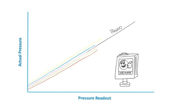
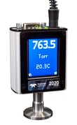
Teledyne vacuum gauges are very good selection for use in Argon. The HVG-2020B (Click Here) is an excellent choice for measuring Ar from below 1 mTorr up to atmosphere. Convection driven pirani vacuum gauges, when used with gases other than N2/air can have curious behavior as can be seen in the cartoon below.

Convection driven pirani vacuum gauges cartoon

The HVG-2020B vacuum gauge uses a gas-independent piezoresitive sensor that does not rely on convection affects and provides a more linear response to Argon across the entire measurement range.

Piezoresitive sensor cartoon     HVG 2020A_76307_finger

If you would like more information about either the 300 Vue mass flow meters or controllers, or any of our vacuum gauges including the HVG-2020B, you can talk to any of our application engineers at 757-723-6531, email hastings_instruments@teledyne.com, or LiveChat with us at www.teledyne-hi.com

CONTACT US FOR MORE INFORMATION

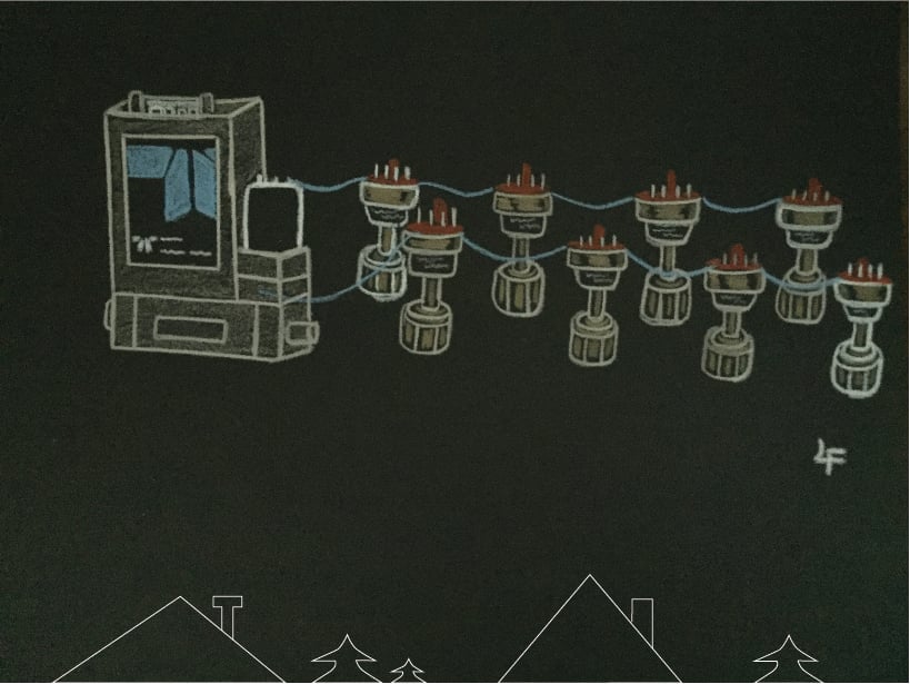
Special thanks to Lawrence Ferbee from the stockroom for his cartooning skills. If you would like to see Lawrence in action as he draws, check out our HVG-2020B video:

https://www.youtube.com/watch?v=_Bk3Q7SpSUc


Tags: Argon Gas

What is a Pirani Vacuum Gauge?

Posted by Doug Baker on Wed, Dec 01, 2021 @ 10:44 AM

A Pirani vacuum gauge is a type of thermal conductivity gauge that is also often referred to as a “thermal heat transfer gauge”. In a Pirani gauge, the rate of heat transfer is a function of the number of gas molecules present in the vacuum system. Pirani gauges are capable of providing reliable pressure measurement in a wide variety of vacuum technology applications.

What is the working principle of the Pirani Vacuum Gauge?

Pirani GaugeA Pirani vacuum gauge contains a heated component, such as a wire or thin-film membrane (see figure on right), which is brought to an elevated temperature, typically through the use of a bridge circuit. As changes in gas molecular density occur, the transfer of heat from the wire to the gas is affected. This heat loss is dependent on gas type and pressure, and the amount of energy required to keep the wire at temperature varies accordingly. Consequently, the amount of energy is dependent on vacuum pressure and can be converted to a pressure value.

Accurate pressure measurement depends on the ability of the bridge circuit to maintain very precise control of the sensor’s temperature. The most common technique is to use a Wheatstone bridge circuit. In one design of a Pirani bridge circuit, two legs of the bridge are controlled at the same voltage via an electronic feedback loop. The measurement technique then is to quantitate the power required to maintain the heated sensor at a given temperature above ambient. (See J. Vac. Sci. Technol. A 13(6), Nov/Dec 1995)

In the case of a gauge that employs a heated sensor wire, there are three main heat loss routes: bulk thermal conduction via the wire and its supports, radiation losses, and thermal conduction losses through the gas. It follows that a well-designed Pirani vacuum gauge minimizes loss of signal due to radiation and bulk thermal conduction. Radiation losses are strongly (fourth power) dependent on the temperature of the heated sensor. Consequently, when operating a Pirani gauge, it is important to keep the sensor at a low enough temperature such that the radiation loss mechanism does not dominate the overall signal. Similarly, a well-designed Pirani gauge minimizes bulk thermal conductivity via the sensor element. For both radiation and bulk thermal conductivity losses, the loss factors are dependent on temperature.

What are the advantages of the Pirani Vacuum Gauge?

The Pirani vacuum gauge offers numerous advantages. Foremost, the gauges are typically very easy to use and can provide years of trouble-free, reliable pressure measurement, because they have no moving parts. Additionally, they are highly economical, costing far less than capacitance manometers. Flexibility in output monitoring includes local displays, analog output, and/or digital communication. Pirani vacuum gauges are relatively fast and are very responsive to changes in the vacuum system’s pressure. Gauges with very small internal dimensions can offer increased response speed. It should be noted that convection-enhanced Pirani vacuum gauges require larger volumes to support convection currents and may therefore have slower response, simply due to the larger volume that must be evacuated inside the tube. Convection-enhanced Pirani vacuum gauges measure pressure up to atmospheric pressure, however, their accuracy in gases other than air or nitrogen at elevated pressure, can be very poor.

Combination gauges, such as Teledyne Hastings’ HVG-2020B, combine a piezo-based sensor with a conventional, thermal-based Pirani sensor to provide accurate pressure measurement from 10-4 Torr (0.1 mTorr) to 10+3 Torr.  Additionally, by combining the two technologies in one gauge, the errors associated with the gas composition specific Pirani sensor are eliminated at pressures above 10 Torr.

What are some of the applications for Pirani Vacuum Gauges?

Many Pirani vacuum gauges measure pressure from below 1 mTorr up to atmosphere and are a very good choice for a wide variety of applications:

  • Pirani vacuum gauges are used to monitor the pump down from atmosphere to the start of the high vacuum region (where turbomolecular pumps or other high-vacuum pumps take over)
  • In the vacuum metallurgy industry (high-purity alloys manufactured in a controlled environment) Pirani vacuum gauges ensure process consistency and optimization of different thin-film coating systems.
  • Freeze dryers and vacuum dryers frequently operate in a vacuum region that is well-suited to Pirani vacuum gauges, as well as the manufacture and maintenance of cooling systems (air conditioning, ice machines, and refrigeration).
  • Various analytical instrumentation requires vacuum levels in and below the mTorr region, and the Pirani gauge is often the most cost-effective instrument for these applications.

FAQs

What are some best practices for Pirani Vacuum Gauges?

Pirani gauges have no moving parts and generally do not require maintenance. It should be noted that this type of gauge is susceptible to contamination, especially in oil-based pumping systems. In systems with contamination, the gauge tube should be installed with the port facing downward to reduce oil accumulation inside the tube. 

Convection-driven Pirani vacuum gauges should always be installed with the cylindrical axis parallel to the floor. Failure to install this type of gauge properly will lead to erroneous readings above the rough vacuum level. 

If the vacuum system has excessive oil vapor or other contaminants, a molecular sieve filter can be used to extend the service life of the gauge.

For information on Teledyne Hastings Vacuum Gauges, visit https://www.teledyne-hi.com/products-services/vacuum-measurement-and-control or click the button below to contact us for more information.

Contact Us

Tags: Pirani Vacuum Gauge

Vacuum Gauge Series: What is a Thermal Couple Gauge?

Posted by Devin Seran on Mon, Apr 12, 2021 @ 04:02 PM

What is a Thermocouple Gauge?

Vacuum Gauge Series - Thermocouple Gauge Tubes Fun Fact

Teledyne Hastings was founded in 1944 as “The Hastings Instrument Company” by Charles and Mary Hastings. The introduction of thermal sensing technology in late 1940s at the young company offered potential for a variety of new technologies and quickly became the foundation for many early Hastings’ instruments. Early products included air velocity indicators, thermal mass flow meters, stack emission monitors and, of course, the thermocouple vacuum gauge tube.

By 1964, Hastings Instruments had grown into one of the leading vacuum and thermal mass flow instrument companies in America. Today, our popular Thermocouple Vacuum Gauge Tube product lines, including the DV-4, DV-5, and DV-6, are trusted globally where repeatable, rugged, and dependable pressure measurement is needed. Based in Hampton, Virginia for over 75 years, the highly-skilled employees at Teledyne Hastings are dedicated to delivering thermocouple vacuum gauges of exceptional quality.

Teledyne Hastings Gauge Tubes

How does a thermocouple gauge tube work?

The physics behind how a thermocouple vacuum gauge tube functions is simple. For example, let’s look at the DV-6R thermocouple vacuum gauge tube, which is capable of pressure measurements within the range of 0 – 1000 mTorr. The DV-6R can be seen in the image below, along with the representative schematic.

Vacuum Gauge Tube Illustration DV-6R-resized-183

A thermocouple consists of a junction of two dissimilar filaments that are soldered together. Three thermocouples are shown (A, B, and C) in the DV-6R diagram, and many thermocouple gauge tubes use multiple thermocouples to form a thermocouple array. At each junction, there is a small voltage (on the order of a mv) which is a function of temperature. When the gauge tube is in operation, thermocouples A and B are resistively heated inside the gauge tube’s housing. Because each filament connected to both A and B thermocouples is exposed to the gas in the vacuum, thermal energy is transferred away from the array at a rate which is dependent on the number of collisions between the gas molecules and the filament wires.  This transfer of thermal energy is, in turn, dependent on the pressure inside the tube. In essence, by measuring the rate of thermal energy transfer, the pressure inside of the tube is indirectly determined!

To understand the concept more fully, let’s consider two extremes. In high vacuum, where the pressure is very low, there will be fewer gas molecules to collide with each filament and the tube’s voltage output will be relatively high. Higher temperature corresponds to higher thermocouple output. As we approach near atmospheric pressure (760 torr), there are more gas molecules, resulting in more thermal energy transferred away from the filament. Consequently the thermocouples run at a lower temperature resulting in a relatively low output. The varying output produced by the thermocouple gauge is dependent on the thermal conductivity of the gas in the vacuum system, which is then used to measure pressure.

Thermocouple vacuum gauges are “indirect gauges”, meaning they accomplish pressure measurement by measuring a physical property, such as thermal conductivity or ionization rate of gas molecules, to determine the pressure in a vacuum system.

How to use a thermocouple vacuum gauge tube:

Teledyne Hastings’ vacuum gauge tubes are manufactured to the highest quality and tested to be extremely repeatable from one gauge tube to another to ensure accurate process control. Thermocouple vacuum gauge tubes are physically installed on a vacuum system and then used to measure various pressures across the tube’s full scale range. When the filament inside the tube is excited, the output is then converted to a pressure measurement.

An example gauge tube installation would consist of a DV-6R thermocouple vacuum gauge tube connected to a DCVT-6 panel meter or HPM-4/5/6 handheld meter. Both the DCVT-6 and HPM-4/5/6, are factory configured to work seamlessly with DV-6R gauge tubes, out of the box. The output from the gauge tube is then monitored by the DCVT-6 or HPM-4/5/6 and the level of vacuum displayed.

In the case of the DCVT, two contact relays are available for process control, and the dual relays will independently toggle according to user-defined setpoints, when the vacuum setpoint has been crossed. This demonstrates how the factory-tested repeatability of our gauge tubes results in consistent and repeatable process control! The DCVT also provides serial communication (RS232), LabVIEW™ drivers and linearized analog output options (0-1 VDC, 0-5 VDC, 0-10 VDC, 4-20 mA).

Related Products

Teledyne Hastings' Vacuum Products
DCVT-6 HPM 4/5/6 DV-6R DV-6S
Model DCVT-6 Vacuum Gauge

HPM

DV-6R-resized-183 DV-6S-1

Application Example:

Gas Plant Tanks 182395563There are numerous, diverse vacuum applications and different vacuum systems can require specific thermocouple vacuum gauge tubes. At the most basic level, vacuum systems can be installed in a variety of environments including outdoor with exposure to weather elements, indoor industrial and laboratory conditions in which exceptionally high cleanliness standards are required.

A good example of how a thermocouple vacuum gauge tube meets the requirements of a specific application, is presented in the vacuum insulation or vacuum jacketing field. The technique of using a vacuum guard or barrier to thermally insulate a cryogenic or refrigerant tank is straightforward: by removing the air from around an object, conductive heat transfer is eliminated. The better the vacuum attained, the higher the level of vacuum insulation. To effectively measure pressure below the 1 Torr range, a vacuum dial gauge is simply not sensitive enough; a thermocouple vacuum gauge tube is required.

To obtain vacuum readings from DV-6 gauge tubes, a dedicated electronic display or handheld battery-operated readout is used. The Teledyne Hastings’ DCVT provides continuous monitoring via an easy to read LED display. For periodic vacuum monitoring of one or more tubes, the hand-held HPM 4/5/6 is recommended because of its portability (9V battery power) and its ability to be quickly connected to a DV-6 tube and obtain an accurate reading with fast response time. To ensure the most accurate measurement, the DB-20 Reference Tube can be used to validate the electronic calibration. This can assist in determining if the thermocouple vacuum gauge tube requires replacement by ensuring that it is producing an accurate reading.

Teledyne Hastings has created a detailed application note on vacuum jacketing insulation at this link.

For more information about any of our thermocouple sensor series or vacuum gauges, we are here to help. In addition to LiveChat on our website, you can contact us at hastings_instruments@teledyne.com or call 757-723-6531 (800-950-2468) or click the button below.

Contact Us

Tags: vacuum gauges, Thermocouple Gauge Tubes

Women's History Month - Celebrating Mary Hastings

Posted by Doug Baker on Mon, Mar 08, 2021 @ 10:00 AM

Mary HastingsMarch is Women’s History Month and this year we’d like to focus on Mary Hastings, one of the key founders of Hastings Instruments. Mary Comstock graduated from William & Mary with a degree in physics with minors in math and chemistry. She was truly a pioneer in many ways. After college, she took a job as a “computer” at NACA (National Advisory Committee for Aeronautics) in Hampton, Virginia. There, Mary met Charles Hastings, a young engineer who had his office across the hall from her. The two were married in 1940.

In a business era that was almost thoroughly dominated by men, Mary was an invaluable contributor to the success of Hastings Instruments. She promoted the fledgling company through press releases that she prepared for local papers and thereby helped to secure critical financial support. She attended shareholder meetings of other companies to learn how they conducted their annual meetings. For many years, Mary prepared the annual report for Hastings shareholders. In short, she was not afraid to tackle any challenge that would help grow the company. Moreover, Mary was a constant voice of wisdom to her husband with respect to company decisions and policy. She accomplished all of these things while the couple raised three children.

It is reasonable to assume that without Mary Hastings, the company would not have been nearly as successful. So during Women’s History Month, we want to celebrate her many accomplishments. You can hear more about Mary from her daughter Carol Hastings Sanders in this video:

https://www.youtube.com/watch?v=AxdFQQXEEzQ

Carol Hastings


Tags: Teledyne Hastings Instruments

Freeze Drying of Flowers - Happy Valentine's Day!

Posted by Doug Baker on Fri, Feb 12, 2021 @ 08:57 AM

freeze dried flowers courtsey of Flowers ForeverHappy Valentine’s Day 2021! Time for me to run out and order some freeze-dried flowers for my wife. What?... yes, it’s true! In case you have not heard of this, freeze-dried flowers can make a beautiful gift.


According to Flowers Forever – Bellabeads of Columbia SC, https://myflowersforeverjewelry.com/pages/freeze-dried-flowers, freeze-dried flowers will, “retain their beauty as if frozen in time as a lasting memento.” They can be placed in shadow boxes or frames and stored for many years.

So this is probably the best time to tell you about this fun application of vacuum technology. I recently worked with one of our vacuum customers who services freeze driers for florists, so this topic is “fresh” in my mind. Freeze drying is well-known for use in the manufacturing of food and drugs. Most likely, you have something in your house that has been processed with freeze-drying. So, let’s take a closer look.


Freeze dried raspberriesFreeze drying, also known as lyophilization, is a process in which water molecules are removed from biological cells without damaging the cell structure. For starters, the product to be freeze-dried is chilled and the water inside is completely frozen (i.e. placed in the solid state). Next, the pressure is reduced using vacuum pumps and the water molecules sublimate – that is, water goes from the solid phase directly to the gas phase.


The gas load due to the water vapor is usually very high and requires condensers to trap the liberated water and stop it from overwhelming the pumping system. Commercial freeze driers (see image below) include a heat exchanger which serves two purposes: first, the heat exchanger is used to cool the product and later, it is used to gently heat the product to drive the water sublimation.

Commercial Freeze DrierView inside commercial freeze-drier


Do you know of some other cool applications of vacuum technology, we would “love” to hear from you! Please visit Live chat with us at www.teledyne-hi.com or call 1-800-950-2468.


Special thanks to Flowers Forever – Bellabeads for the use of flower image from their beautiful website.

Tags: Vacuum gauge

Carbon Dioxide (CO2)

Posted by Doug Baker on Tue, Feb 09, 2021 @ 03:07 PM

Carbon Dioxide Molecule_1041722966

This blog is the next installment in a series of blogs focusing on industrial gases. The first blog featured SF6 and can be found here:   https://info.teledyne-hi.com/blog/sulfur-hexafluoride-gas-sf6 In this blog, we will explore one of the most useful, and well-known, of the industrial gases, carbon dioxide (CO2).

CO2 is an odorless and colorless gas. As a matter of fact, you exhale about a quarter liter of CO2 every minute (https://www.nytimes.com/1990/08/14/science/q-a-burden-of-breathing.html). And while we are on the subject of breathing, it is interesting to note that it is usually the buildup of CO2 that triggers a breath, not the lack of oxygen. A recent special feature in Gasworld US Edition noted that “low concentrations are not harmful, higher concentrations can affect respiratory function, cause excitation and depression of the central nervous system.”

The structure of CO2 is linear. The electronic structure of the molecule features bonding pairs of electrons around the central carbon atom. These electron pairs repel equally while bonding to oxygen atoms. The equal repulsion is what gives CO2 its linear arrangement. A diagram of the molecule is shown on right.

There are many fascinating uses of CO2, some are well-known while others may be new to the reader.

  • Used in industry to produce chemicals and as feedstock
  • Used in the metals industry to improve the hardness of castings
  • Often used as a carrier for spraying of paints or for spraying vegetable oils in cooking
  • Liquid CO2 can be used as a solvent in eco-friendly dry cleaning
  • Solid CO2 can be used for cold storage
  • Jets of CO2 are used for special effects in movies, live shows, and amusement parks
  • Gas phase CO2 is used for fire extinguishers
  • Carbonated beverages

A quick note on purity... CO2 used for fire extinguishers can be ~ 95% pure. However, the purity of CO2 in carbonated beverages can be as high as 99.9995%.

Hastings CO2 Collage

A word on explosive decompression of elastomers when using CO2. CO2 is known to more easily penetrate elastomeric seals such as o-rings and diaphragms at pressures significantly higher than atmosphere which in turn can cause the host material to swell. If the pressure is suddenly decreased (i.e rapid decompression), the internal gas can rupture the elastomer and the seal can be compromised. There are a few things the user can try to reduce risk. First, select materials that are less susceptible. Viton® is often not a good choice for CO2 applications. Second, if the application will allow, try to reduce the amount of time the elastomeric seal is held at elevated pressure. And third, when the pressure is reduced, allow more time for the CO2 to exit the material.

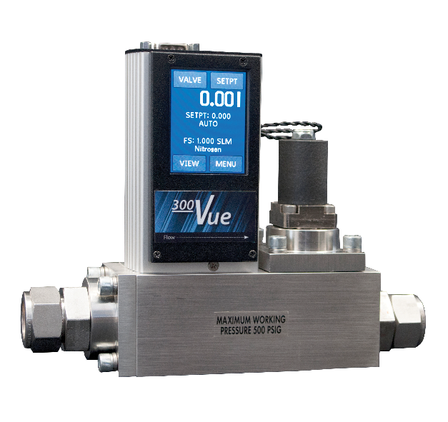
Flow controllers from Teledyne Hastings are used to measure and control CO2 flow in many of the aforementioned applications. The 300 Vue can provide all-metal seals and Kalrez® valve seat. (see diagram below). For users of the elastomeric-sealed 200 Series, we recommend Buna-N seals which are less susceptible to explosive decompression.

Mass Flow Cutaway

Teledyne vacuum gauges can be used with CO2. The HVG-2020B (Click Here) is an excellent choice for measuring CO2 from below 1 mTorr up to atmosphere. Convection driven pirani vacuum gauges, when used with gases other than N2/air can have curious behavior as can be seen in the cartoon below.

Convection driven pirani vacuum gauges cartoon

The HVG-2020B vacuum gauge uses a gas-independent piezoresitive sensor that does not rely on convection affects and provides a more liner response to CO2 across the entire measurement range.

Piezoresitive sensor cartoon

HVG 2020B Angle Finger 20.9C


If you would like more information about either the 300 Vue mass flow meters or controllers, or any of our vacuum gauges including the HVG-2020B, you can talk to any of our application engineers at 757-723-6531, or email hastings_instruments@teledyne.com or LiveChat with us at www.teledyne-hi.com

Special thanks to Lawrence Ferbee from the stockroom for his cartooning skills. If you would like to see Lawrence in action as he draws these, check out our HVG-2020B video:

https://www.youtube.com/watch?v=_Bk3Q7SpSUc

Viton® is a registered trademark of DuPont Performance Elastomers

Kalrez® is a registered trademark of DuPont Dow Elastomers

Liquefied Nitrogen use in Aluminum Extrusion

Posted by Wayne Lewey on Tue, Nov 24, 2020 @ 12:22 PM

The use of Liquefied N2 (LN2) has revolutionized aluminum extrusion mold performance. CVS Corporation based in Gimpo, South Korea has developed a proprietary LN2 cooling process that allows production output to more than double for some extrusion profiles. Production times vary based on the geometry of the extrusion profile. Ram speed test data can be found in Figure 1 below.

Extrusion Profile Table

Figure 1: Extrusion Profile Table


The Aluminum Extrusion Mold Liquid Nitrogen Cooling System from CVS is designed to control the temperature of both the profile and the mold during the extrusion process. As the billet passes through the extrusion mold, the friction between the billet and the mold creates excess heat. This excess heat limits the extrusion ram speed and is the main cause of reduced productivity in the extrusion process. The CVS process maintains optimum profile and mold temperatures by using automated cryogenic proportional control valves to provide precision dosage of Liquefied N2.

Aluminum Extrustion Mold Liquid Nitrogen Cooling System from CVS

Figure 2: Aluminum Extrusion Mold Liquid Nitrogen Cooling System from CVS

Model DCVT-6 Vacuum Gauge with DV-6R


Figure 3: Model DCVT-6 Vacuum Gauge with DV-6R

To deliver LN2 to the system, CVS employs their own efficient design of vacuum insulated pipe. This design incorporates the model DV-6R thermocouple gauge tube to monitor the vacuum jacket pressure. Mr. Ko Hwa-Jin specified the model DV-6R because of its proven reliability. The CVS production team uses the model DCVT-6 vacuum gauge in conjunction with the DV-6R in manufacturing.

For more detail on effective vacuum jacket insulation, see Teledyne Application Note: Ensuring a Vacuum Jacket is Working Properly​

Mr. Ko Hwa-Jin is the President of CVS Corporation and can be reached by email or website: www.ln2doser.com

Mr. Yoonk Min is the President of Inforad Corp. which is the distributor for Teledyne Hastings Instruments for South Korea. Mr. Min can be reached by email or website: www.inforad.co.kr

Wayne Lewey is the International Sales Manager at Teledyne Hastings Instruments and can be reached by email

Tags: Vacuum gauge, Vacuum Insulated Pipe, Liquefied Nitrogen, Vacuum Gauge Tube, Aluminum Extrusion

Did you know... The 300 Vue mass flow controller has flexible analog and digital output?

Posted by Doug Baker on Thu, Nov 12, 2020 @ 04:26 PM

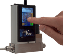
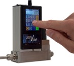
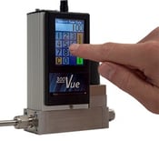
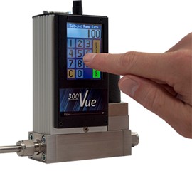
Did you know? Even if your flow controller does not have the color touchscreen display, the 300 Vue flow line still allows you to switch between analog & digital control by using the zero button. (See the diagram below). You can also toggle between RS232 & RS485. This is a convenient feature when users want to switch their setup. Instructions can be found in the manual (pg. 14).


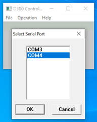
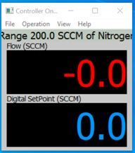
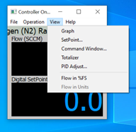
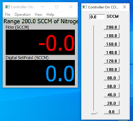
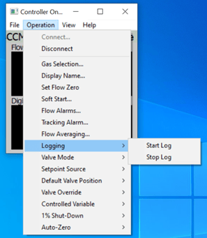
And, of course, we have our free Windows™ software. With the software, you can quickly configure and control your 300 Vue. And you can also record flow data and store to a file If you would like us to send a secure transfer download link for the free software, click here: https://www.teledyne-hi.com/resource-center/software

        300 Vue Top Cover             Vue_Touch_Screen-2


Tags: mass flow controller, mass flow instruments

How do I use GCF (Gas Conversion Factors) with my mass flow meter or mass flow controller?

Posted by Doug Baker on Mon, Nov 02, 2020 @ 09:54 AM

Using thermal mass flow instruments by Teledyne Hastings is an easy way to quickly and accurately measure gas flow. And in some cases, a mass flow instrument may be calibrated for one gas, but then the user may want to use the instrument in another gas. In this blog, we will show how to use GCFs (Gas Conversion Factors) when using flow instruments in different gases.

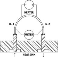
Before we get into GCFs, let’s quickly review the operation of one of our flow sensors. Below, we show a diagram of the 200 Series flow sensor. In this sensor, gas flows through a capillary tube which is heated in the middle to a temperature which is approximately 130°C. Two thermocouples, one upstream (TC-1) and one downstream (TC-2), measure the temperature. The temperature difference between the two thermocouples is proportional to the heat flow through the capillary tube. The heat flow, in turn, is proportional to the mass flow times the specific heat Cp of the gas. So, to first order, if we want to use a thermal mass flow meter that has been set up for one gas, and use it with another gas, we will multiply the output of the meter by the ratio of the specific heats. GCF ~ Cp1 / Cp2

200 Series Sensor

There are a couple of things we need to point out. First, the ratio shown above is a simple approximation and does not tell the whole story. Next, the best GCFs are those that have been measured experimentally. However, in the case of dangerous gases, we use the best thermodynamic data available.

Here is a table of some common GCFs.

Gas Conversion Factors (N2)
  200 Series 300 Series
Helium 1.402 1.400
Oxygen 0.981 0.978
Carbon Dioxide 0.743 0.753
Carbon Monoxide 1.001 1.001
Methane 0.770 0.779
Ammonia 0.781 0.781
Hydrogen 1.009 1.004
Argon 1.401 1.405

Next, we will discuss how we apply GCFs in practice. Let’s take an example of a flow meter that is calibrated for nitrogen. If we wanted to use the flowmeter in argon, we would take the output and multiply by the GCF for Argon.

Argon GCF

Here is another example; suppose we have a meter that is calibrated in helium and we want to use it in hydrogen. You would start by dividing the output by the GCF for helium (think of it as converting to the nitrogen equivalent), and then multiplying by the GCF for hydrogen.

H2 He GCF

Remember, always use the appropriate set of GCFs for the flow series that you are using. In other words, if you are using our Digital 300 Series, don’t apply GCFs from a 200 Series manual – they are not the same. And certainly don’t use non-Teledyne table of GCFs for use with Teledyne flow products. They might get you in the ballpark, but they will not be your best conversion.

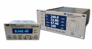
One other quick note about applying GCFs. Our line of flow power supplies, the THCD-101 (single channel) and the THCD-401 (four channel), can be used to quickly scale the analog input which is equivalent to applying a conversion factor. Let’s take another look at the Argon example. If we used the THCD-101 power supply with the nitrogen flow meter as shown below, at the nominal full scale of the flow meter, we will have a 5 VDC signal. If we want to use this same meter and power supply with Argon, we just need to “tell” the THCD-101 what value to display when it receives 5 VDC. So, if our flow meter was calibrated for nitrogen to give 5 VDC at 250 sccm, then the same flow meter will give 5 VDC in argon at 350 sccm. (250 * 1.4 = 350). So, we would then range the THCD-101 for 350 sccm. This can be done from the front panel or via the internal webserver.   

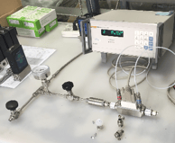
HFM200 with THCD

Now let’s make things a little more interesting and discuss a flow controller example. Analog flow controllers work by receiving a command signal (usually 0-5 VDC, or 4-20 mA) and then they adjust their control valve such that the flow, and thus the analog signal output, matches the command signal input. (You can think of it like the cruise control in your car – you tell it you want to go 78 miles per hour, and then the engine does what it needs to do to maintain that speed). In the case of a 0-5 VDC flow controller, a 5-volt setpoint command is instructing the flow controller to set the flow to 100% of full scale. The relationship between flow rate and command signal is linear, so if the user wanted to control at 25% of full scale, then they would send a 1.25 VDC command signal (0.25 * 5 VDC = 1.25 VDC).

HFC with THCD

Now, suppose we had an HFC-202 flow controller (200 Series) that was calibrated for 200 sccm of methane and we wanted to use it to control the flow of argon. What voltage level would we need on the command signal to have a flow rate of 100 sccm of argon? Let’s first determine the full-scale flow rate (5 VDC) when using argon:

Flow (Ar) = Flow (CH4)/GCF (CH4) * GCF (Ar) = (200 sccm / 0.77) * 1.401 = 363.9

So, a 5 VDC command signal will give us 363.9 sccm of argon. If we want 100 sccm, we would send:

Command Voltage = 100 sccm (5 VDC / 363.9 sccm) = 1.374 VDC.

Now, one important note about using flow controllers in different gases. Just because we can apply GCFs does not mean that a flow controller’s valve will work properly when switching from one gas to another. As an extreme example, a flow controller valve that has an orifice sized to handle hydrogen will have a hard time handling significant flows of large polyatomic molecules like C2H6.

Teledyne flow products are easy to install and use. And our application engineers are standing by to help. We can be reached by email (hastings_instruments@teledyne.com), by phone 757-723-6531, or via LiveChat on our website www.teledyne-hi.com or by clicking the contact us button below.

Contact Us

Tags: Flow Meter, mass flow conversion, mass flow controller, mass flow meter, Gas Conversion