 This is part 1 of a 2-part blog on the Thermal Mass Flow Meter. In Part 1 we will explain the desired characteristics of a mass flow meter (and its sensor). Part 2 will discuss the operation of the Teledyne Hastings 300 Series flow meters (Patent #6,125,695) and how the 300 Series thermal mass flow sensor meets each of the desired characteristics described below.
What is a thermal mass flow meter:
-
Electronic Circuit Card
-
Flow Sensor
-
Bypass Shunt
-
Base
A cutaway is shown in the image on the right.
A flow meter measures the amount of fluid that passes through the meter. At Teledyne Hastings we design our thermal mass flow meters for dry and clean gases. This is useful for wide array applications that include measuring natural gas or air and biogas measurement.
In a typical mass flow meter, gas enters the meter via an upstream port connected to the process to be measured (by Swagelok®, VCR® or other fitting). A majority of the gas passes through the meter’s bypass shunt; however, a certain fraction flows through the meter’s thermal flow sensor.
The meter’s thermal mass flow sensor measures the gas molecular flow that passes through its capillary tube by quantitating thermal energy transfer. The mass flow rate is a function of the gas flow and the specific heat of the gas. The thermal mass flow sensor then provides accurate measurements which can be referenced back to standardized volumetric flow units. Reference conditions (standard temperature and pressure) are based upon the amount of gas flow, which is determined by the number of gas molecules, using the ideal gas law. The meter’s shunt is selected such that the amount of gas moving through the flow sensor is approximately the same at full-scale flow. After passing through the thermal mass flow sensor, the gas then exits the flow meter via a downstream port.
Thermal Mass Flow Meter Characteristics

Ideally, a thermal mass flow sensor will exhibit the following characteristics:
- Linearity: Linearity means that the sensor’s electronic output is directly proportional to the rate of gas flow that is moving through the sensor (within its range). Linearity of the flow sensor leads to the second attribute: Accuracy.
- Accuracy: Accuracy is dependent on the sensor’s Linearity. An accurate flow sensor provides the benefits of better gas thermal flow measurement, flow control and a thorough understanding of the system’s parameters.
- Fast Response: Ideally, the flow sensor would respond instantaneously to a change in the mass flow rate. Aside from the obvious benefit of instant real-time oversight of the process flow, fast response becomes critical when the flow meter is coupled with a proportional control valve to create a thermal mass flow controller.
- Low Differential Drop: For a flow sensor to be ideal for leak testing, it should have a low differential pressure drop across the meter.
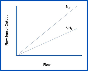
Typically, a mass flow meter is calibrated using nitrogen gas (or in the case of very large flows, it may be calibrated in air). The output of the flow meter can then be scaled for use with other process gases. This means the flow meter technician can calibrate a flow meter for use with a corrosive process gas, such as silane (SiH4), without having to use that specific type of gas. A linear flow sensor will retain its linear behavior as the gas is switched from the calibration gas (N2) to the process gas.
How does a thermal mass flowmeter work?
When gas is flowing through the bypass shunt, a small pressure drop is developed which will direct a fraction of the flow through the arced / semi-circular capillary tubing in the flow sensor. On the outside of the capillary tube, there are two resistive wire coils that act as temperature sensors which are tightly wound and in excellent thermal contact with the tube. These two identical windings are referred to as:
- Upstream Heater Coil (1)
- Downstream Heater Coil (2)
Associated with each of the two heated coils is an ambient coil. The ambient coil is in excellent thermal contact with the aluminum ambient block. Aluminum has a very high thermal conductivity which ensures that both ends of the sensor tube and the two ambient coils (3 and 4) will be at the same temperature.
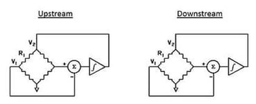
 Two identical Wheatstone resistance bridges are formed from the two pair of coils (see image on right).
The circuit shown in the image on the right is designed to ensure that the heated sensor (upstream and downstream) are maintained at a constant temperature differential (ΔT) above the corresponding ambient coils.
Next, we calculate the power (W) required to maintain ΔT by:

This power will be calculated for both the upstream bridge and the downstream bridge. It can be shown that:
![]()
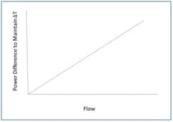
So, by maintaining both heaters at the same temperature difference (ΔT) above ambient, the mass flow rate is directly proportioned to the difference in power (W) between the two bridges. For example, when no flow is passing through the capillary sensor tube, the power needed to maintain that temperature difference (ΔT) will be the same (i.e. ṁ = 0)
As gas flow increases in the tube, heat is transferred from the upstream heater to the gas stream. This will force the upstream circuit to use more power to maintain ΔT. In turn, the gas will transfer heat to the downstream heater which will cause the downstream circuit to use less power to maintain ΔT.
Now, here is the best part: the mass flow rate is directly proportional to the power difference. In other words, Linearity!

Application
Measuring gas flows has become increasingly critical to many processes and the mass flow meter achieves those results with a high level of accuracy. Accurate readings must reference standard temperature and pressure (STP) conditions, without having to correct for temperature and pressure using volumetric flow meters. Typically this requires a temperature compensation for the fluid temperature. Using this method is also not a direct mass measurement because the only direct measurement taken is of the fluid temperature. This can be used for heavy gases such as natural gas or gases as light as hydrogen.
Thermal mass flow meters exhibiting low pressure differentials are ideal for measuring flow in leak testing applications and must provide fast response and accurate gas flow readings.
Teledyne Hastings designed its first fast-response flow meter for leak testing applications in the automotive industry. The low-pressure differential and response speed proved to be highly successful. Today, Teledyne Hastings' Thermal Mass Flow Sensors are used globally in a variety of diverse industries and applications. For more information on Best Practices for Flow Controllers and Thermal Mass Flow Meters download our whitepaper.
Be sure to visit our website for additional information on Teledyne Hastings Mass Flow Controllers and Mass Flow Meters
In our next blog, we will discuss the thermal mass flow sensor at the heart of Teledyne 300 Series of mass flow meters. We will also look at how the 300 Series thermal mass flow sensor meets each of the desired characteristics described above.


 Gases, however, ARE compressible and so the volume is only one factor in determining the amount of material being measured. If we look at the
  An important item to note is that the STP conditions are not actually present during the calibration of