Thermal mass flow measurement instruments are typically separated into two main categories: Mass Flow Meters and Mass Flow Controllers. It’s estimated that over 90% of mass flow measurement instruments sold are mass flow controllers. So, it’s no surprise that most mass flow application conversations focus on mass flow controllers. Notwithstanding, there are still numerous applications for which mass flow meters are critical.
The following are common applications for mass flow meters (also known as thermal mass flow meters):
| Leak Detection | Gas Custody Transfer | Air Quality Monitoring |
| Porosity Measurement | Filter Testing | Fuel Cell Testing |
| Vacuum Pump Performance | Compressor Performance | Valve Performance |
| Calibration Transfer Standard | Combustion Gas Monitoring | Gas Sampling |
| Radiation Monitoring | Welding Shield Gas Monitoring | Thermal Spraying |
One popular application for mass flow meters is leak testing. It’s often used on products where failure is not an option. For that reason, it is widely accepted in the aerospace, automotive, and medical industries. High throughput leak detection using mass flow meters is a nondestructive testing method that offers a fast, clean, precise, and affordable solution for parts manufacturers seeking to perform leak testing on 100% of their products.

A typical test stand is shown in Figure 1. For high throughput leak detection, a pressurized manifold has multiple connections for mass flow meters. On the outlet side of each flow meter is an isolation valve and the test part. When the isolation valve is opened, test part leaks will be noted by the movement of clean dry air across the flow meter. The test part is only exposed to clean dry air.
How does leak detection with mass flow meters compare to alternative methods? It’s faster than pressure decay testing and helium leak detectors. It’s also cleaner than hydrotesting, bubble testing, and liquid penetrate testing.
To learn more, visit our Application Note:
Common products for which high throughput leak detection has been implemented include:
- Automotive Parts such as fuel injectors, brake components, exhaust systems, emission components, fuel pumps, fuel tanks, power steering systems, air conditioning systems, engine blocks, cylinder heads, transmission castings
- Aerospace Parts such as jet engine components, heat exchangers, cabin valves, oxygen delivery systems, hydraulic systems, air conditioning systems, brake systems
- Other: medical devices, filters, space suits, and much more


Frequently Asked Questions (FAQS)
Q: What’s the difference between a thermal mass flow meter and mass flow controller?
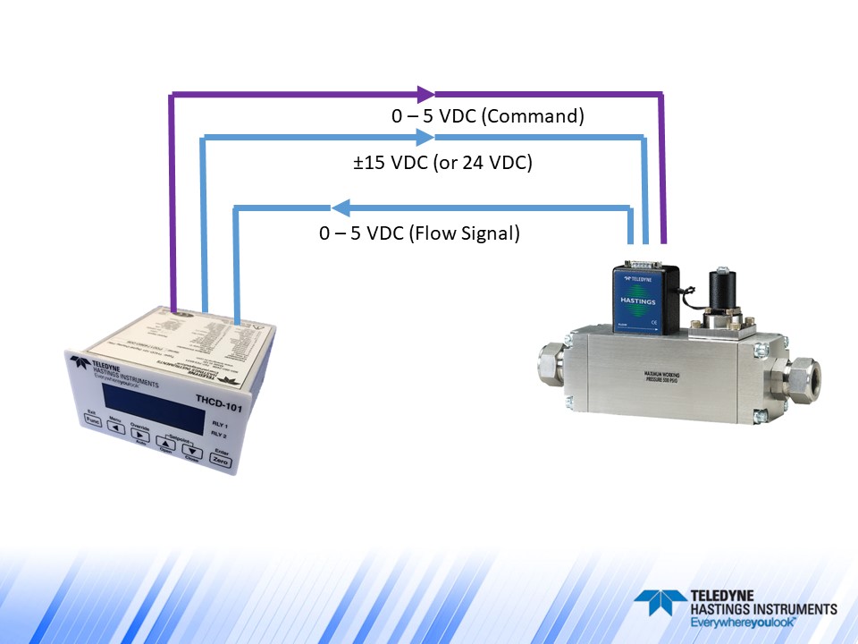
A: A thermal mass flow meter measures flow using a thermal flow sensor but does not include a proportional control valve and does not control gas flow. While a thermal mass flow controller will both measure and control gas flow, according to a command signal (setpoint). For accurate flow control, the controller measures and adjusts the gas flow using a precise, proportional control valve to maintain stable control of the flow rate based on the readings from the heated sensor.
Q: Are thermal flow meters gas specific?
A: A thermal mass flow meter is built for a user’s specific operating conditions. Teledyne Hastings' thermal flow meters are thermal based, so measurements are gas specific. For example, there would be a difference in heat conductivity between natural gas vs compressed air. Our thermal mass flow meters are built to cover a user's flow range and gas type.
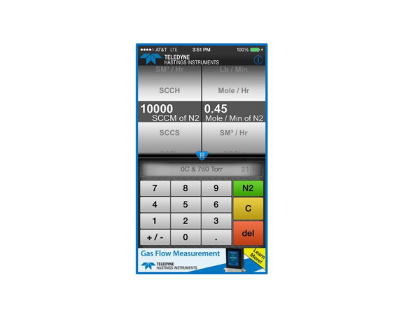
Q: What does SCCM stand for?
A: SCCM stands for Standard Cubic Centimeters per Minute. This is a unit of measure for gas molecular flow rate (often referred to as mass flow). In standardized volumetric flow units, the reference conditions, or “STP" temperature and pressure, define the amount of gas by determining the number of gas molecules using the Ideal Gas Law.

 There are many benefits for having a Flow Service Plan for your Mass Flow Meters/Controllers. This blog touches on just a few of them.
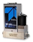 Each instrument under the plan is eligible for three calibrations anytime within a 36-month period. Under the discount Flow Service Plan, the user purchases two calibrations and receives a third at no cost. At the time of purchase, the user may specify a calibration interval; Hastings Service will track the unit’s history and provide advance notice (four weeks) of the next scheduled calibration.
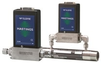 The calibration and service department will clean, recalibrate, and ship the instrument back to the user within 5 working days or less per instrument. The Flow Service Plan will improve up-time at the user’s facility while ensuring compliance to metrology requirements. All calibration performed at Teledyne Hastings is traceable to the National Institute of Standards and Technology (NIST). In addition to this, calibrations are compliant to ISO 17025 requirements.
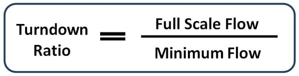
 A flow meter with a large turndown ratio will have a large operating range. This can also be indicative of the flow meter’s cost. For example, variable area flow meters (rotameters) typically have lower turndown ratios compared to thermal mass flow meters.
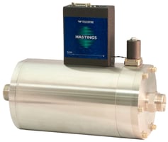 Most analog mass flow controllers also have an accuracy of ± 1% FS. However, they typically have an automatic valve shut circuit that closes the valve at flow rates below 2% of FS. This is to ensure full valve closure in the event of a small zero offset. The usable range is from 2% to 100%. Since measurement is not possible below 2%, these will have a turndown ratio of 100/2 = 50/1 or 50:1.
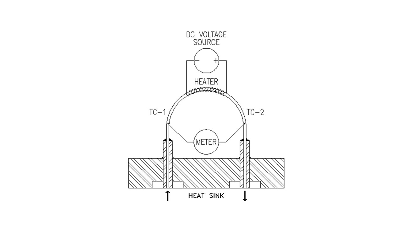
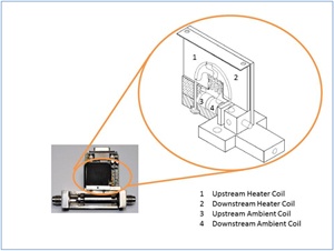 In our previous blog, we showed a cutaway of a thermal mass flow meter. Now let’s take an inside look at the 300 series flow sensor:
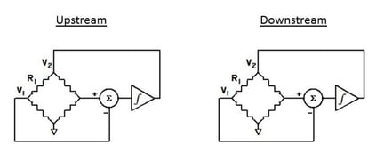 Two identical Wheatstone resistance bridges are formed from the two pair of coils (see image on right).
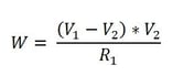
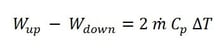
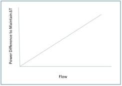 Now, here is the best part: the mass flow rate is directly proportional to the power difference. In other words,
 Last month, we passed our ISO 9001 surveillance audit. It has been over twenty years since we first obtained ISO and we wanted to take a step back and review some significant accomplishments.
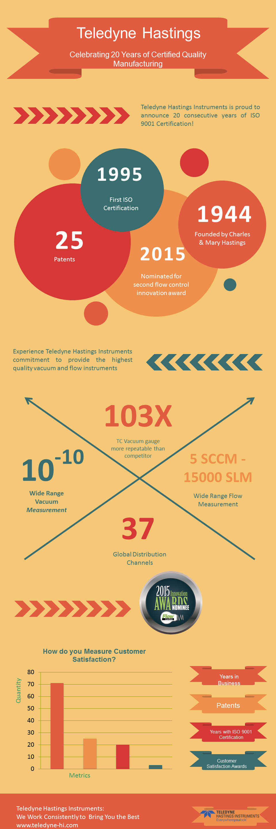
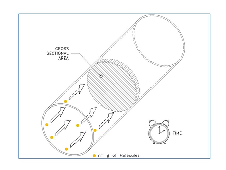
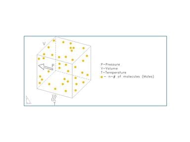
 Gases, however, ARE compressible and so the volume is only one factor in determining the amount of material being measured. If we look at the
  An important item to note is that the STP conditions are not actually present during the calibration of