Have questions? Need Help?
757.723.6531 | 800.950.2468

Teledyne Hastings Instruments Blog

The Teledyne Hastings Team

Recent Posts

Mass Flow Rate vs Volumetric Flow Rate

Posted by The Teledyne Hastings Team on Fri, Mar 08, 2024 @ 12:40 PM

When selecting a flow meter or flow controller for gases, it is important to understand the difference between the mass flow rate and volumetric flow rate. Unlike liquids, gases do not have a constant volume. The volume of a gas changes as the temperature and pressure change.

Referencing the Ideal Gas Law: PV=nRT

  • When the temperature of a gas increases, the volume increases.
  • When the temperature of a gas decreases, the volume decreases.
  • When the pressure of a gas increases, the volume decreases.
  • When the pressure of a gas decreases, the volume increases.

When you only know the volume or volumetric flow rate of a gas, you may not actually know how much gas you have. In this blog, we compare mass flow rate vs volumetric flow rate, how each are measured, and the advantages of each.


What is Mass Flow?

Hastings’ first thermal mass flow meter was introduced in the 1960s, and the phrase “mass flow” has been commonly used. However, the phrase “mass flow” is a bit of a misnomer. Thermal mass flow meters actually measure the flow rate of gas molecules or the molecular flow rate. Since the mass flow meter or controller measures the molecular flow rate, it is independent of temperature and pressure changes. It is not necessary to separately measure temperature and pressure, and temperature and pressure corrections are not required.

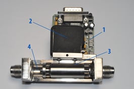
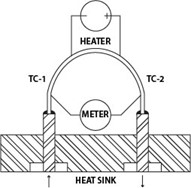
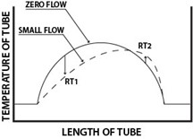
Teledyne Hastings Instruments mass flow meters and mass flow controllers use a thermal flow sensor to measure the molecular flow rate. The flow sensor is heated, and the flowing gas molecules transfer or “carry” the heat downstream. The rate of heat transfer is proportional to the mass / number of gas molecules flowing through the sensor which is used to determine the flow measurements.

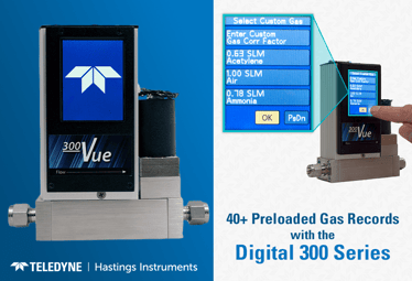
Mass flow rates can be expressed in true mass flow units such as LB/hr, Kg/hr, and g/sec. However, they can also be expressed in standard volumetric flow rates such as SCCM, SLM, and SCFM. Standard volumetric flow units look like volumetric flow units, but they are mass flow units. Standard units are referenced to Standard Temperature and Pressure (STP). STP must always be defined. Teledyne Hastings Instruments typically uses STP: 0° C & 760 Torr; however, other STPs can be specified.


What Should Mass Flow Rate be Used For?

Mass flow rate measurement is ideal for any application where gas measurement is critical. As stated earlier, there is no need to simultaneously measure gas temperature and gas pressure which can introduce errors to your calculations. It’s ideal for applications requiring fast, reliable, repeatable, and accurate measurements.

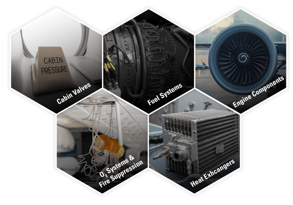
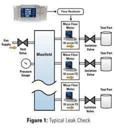
Some common applications include instrument calibration, air sampling, non-destructive leak testing, gas blending (mixing), thermal spraying, thin film deposition, analytical instrumentation, and many more.


What is Volumetric Flow?

Volumetric flow rate is mathematically defined as the cross-sectional area of a tube multiplied by the velocity of the fluid. It simply measures volume per unit of time. Volumetric flow is ideal for liquids since their volume mostly cannot change. When using volumetric flow meters for gas measurement, the only way to determine how much gas is flowing is to calculate it. That requires either maintaining constant temperature and pressure or simultaneously measuring them. Examples of volumetric flow methods include rotameters, turbine meters, and critical orifices.

One of the most common volumetric flow meters is a rotameter or variable-area flow meter. It consists of a tapered tube and a float. The tapered tube is typically constructed of glass to allow the user to visually see the float. As the flow rate increases, the float travels up the tapered tube. The tube has graduated lines to indicate the volumetric flow rate.

Some common volumetric flow units are GPM, L/s, and CFM. Mass flow can be calculated from volumetric flow only if the density (ρ) is known. Qmass = Qvol*ρ.


What Should Volumetric Flow Rate be Used For?

Volumetric flow rates are fine in applications where the volume is constant such as incompressible liquids. They can also be found in gas applications where the temperature and pressure are fixed. In addition, volumetric flow meters typically have a lower initial cost than a mass flow meter. They are often found in low-cost gas measurement applications where molecular flow rate accuracy is not critical. When molecular flow rate accuracy is required, the user typically measures temperature and pressure separately and calculates it.


Summary

Both mass flow meters and volumetric flow meters are commonly used to measure gas and liquid flow measurements. For gas flow measurement, mass flow is more trusted as it measures the gas molecular flow rate. Mass flow meters and controllers function independently of gas temperature and gas pressure changes. This makes mass flow meters and controllers ideal for applications requiring fast, reliable, repeatable, and accurate measurements. Volumetric flow meters such as rotameters or critical orifice devices cannot routinely achieve these high accuracy levels on gases due to inherent inaccuracies and variations that occur as a result of pressure and temperature changes.

CONTACT US FOR MORE INFORMATION


FAQS

  • Q: Can Teledyne Hastings’ flow meters be used with liquids or any fluid?  
    A: No. Teledyne Hastings’ flow meters cannot be used with liquids. A fluid is defined as “a substance without a shape and can be either a gas or liquid”. Fluids used in our flow meters must be in the gas phase (gases only).

  • Q: What is STP (Standard Temperature and Pressure)?
    A: In standardized volumetric flow units (SCCM, SLM, SCFM), the reference conditions, or “STP” temperature and pressure, define the amount of gas by determining the number of molecules using the Ideal Gas Law. In most cases, the selected reference conditions are 0°C & 760 Torr. Other reference conditions are also used, such as 20°C & 760 Torr, or 70°F & 760 Torr.

  • Q: What does SCCM stand for?
    A: SCCM stands for Standard Cubic Centimeters per Minute. This is a unit of measure for volumetric flow. In standardized volumetric flow units, the reference conditions, or “STP" temperature and pressure, define the amount of gas by determining the number of gas molecules using the Ideal Gas Law.
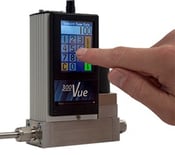
Tags: Mass Flow Rate vs Volumetric Flow Rate

Thermal Mass Flow Meter Calibration

Posted by The Teledyne Hastings Team on Fri, Jan 26, 2024 @ 10:00 AM

Flow Controller
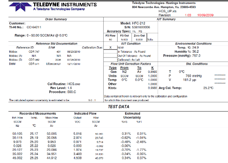
Calibration is the cornerstone of measurement accuracy, ensuring that instruments deliver reliable and precise data. Thermal mass flow meters play a pivotal role in providing a dependable solution for various industries. The calibration of these instruments is a critical factor that demands meticulous attention. In this blog, we delve into the intricacies of thermal mass flow calibration, unraveling the science behind it and its significance in achieving accurate measurements.


The Basics: What is Thermal Mass Flow Meter Calibration?

Teledyne Hastings’s flow meters and flow controllers use thermal mass flow sensors. The Teledyne Hastings Instruments 200 Series thermal mass flow meters operate on the principle of heat transfer using thermocouple technology. The flow sensor consists of a capillary tube that is heated at the midpoint. Thermocouples are used to measure the temperature on both the inlet and outlet ends of the tube. As gas molecules travel through the flow sensor, heat is transferred downstream. The temperature differential between inlet and outlet correlates to the molecular flow rate of the gases. The molecular flow rate is directly proportional to the mass flow rate of the fluid. This relationship forms the basis for the calibration process, as accurate calibration ensures that the meter provides reliable measurements across a range of flow rates and conditions.

Calibration is indispensable for maintaining the accuracy and reliability of thermal mass flow meters. Over time, factors such as contamination, sensor degradation, environmental changes, or wear and tear can impact the meter's performance. Calibration allows for the correction of these deviations, ensuring that the meter consistently produces accurate readings. Moreover, many industries are subject to regulatory standards that mandate regular calibration to guarantee the reliability of the data collected.


How To Calibrate Your Mass Flow Meter

Calibration Reference
  1. The first step in thermal mass flow calibration is establishing a reference standard. This is typically a device with a known and traceable accuracy. The reference standard is used to compare and verify the accuracy of the mass flow meter being calibrated. This can be a reference standard or another flow meter. A high accuracy 300 Vue thermal mass flow meter or mass flow controller with local touchscreen display would create a standard that the unit under calibration will match to.

  2. Calibration involves subjecting the flow meter to controlled flow rates covering its entire operating range. The meter's response to these different flow conditions is carefully observed and compared to the reference standard. The best calibration would be used with actual gas to get the most accurate data points. Since the actual gas (e.g. Helium) could be expensive or rare, then a more accessible gas such as N2 or Air is used with a conversion factor to calculate the actual flow rate in the desired gas.

  3. As the flow meter undergoes calibration, data on its performance at various flow rates is collected. This data is then analyzed to identify any deviations from the reference standard. The reference temperature and pressure may differ from the actual process temperature and pressure. Calibration software may be employed to streamline this process.

    Calibration Report
  4.  If discrepancies are detected, adjustments are made to the thermal mass flow meter to correct its readings. This may involve recalibrating sensor elements or updating compensation factors. The goal is to align the meter's measurements with the reference standard. It is important to note how large these discrepancies are as it may require repair instead of calibration.


Tags: Thermal Mass Flow Meter

Working Principle of Thermal Mass Flow Meters

Posted by The Teledyne Hastings Team on Thu, Jan 25, 2024 @ 03:32 PM

HFC-D-302B

In the world of fluid dynamics and process control, selecting the appropriate flow measurement parameter is crucial for accurate and reliable data. Teledyne Hastings’s uses heat transfer technology to indirectly measure the molecular flow rate of dry gases. Our instruments can be used with volumetric flow units as they are converted to find the mass flow rate.


CONTACT US FOR MORE INFORMATION


What is the Thermal Mass Flow Meter Working Principle?

Basic Design:Basic Principle Flow Meter - 4 Components

A mass flow meter consists of four basic components:

  1. Electronic Circuit Board
  2. Flow Sensor
  3. Bypass Shunt
  4. Base

*See Figure on right


In the world of fluid dynamics and process control, selecting the appropriate flow measurement parameter is crucial for accurate and reliable data. Teledyne Hastings’s uses heat transfer technology to indirectly measure the molecular flow rate of dry gases. Our instruments can be used with volumetric flow units as they are converted to find the mass flow rate.


200Series Sensor Design200 Series graph


There are numerous thermal mass flow sensor designs.  The Teledyne Hastings’ 200 Series sensor is shown in image on left.  This thermal mass flow sensor consists of a small 316SS capillary tube with a heater winding located in the center.  A thermocouple (TC-1) is located on the inlet side and another thermocouple (TC-2) is located on the outlet side.  At zero flow (no gas flow), the heat is transferred through the capillary tube in both directions towards the two thermocouples, each of which has the same temperature (see image on right, ZERO FLOW condition).  As gas flow moves through the capillary tube (inlet to outlet), heat is then transferred downstream by the gas molecules.  The temperature of TC-2 will increase, while the temperature of TC-1 will decrease.  This temperature differential correlates to the molecular flow rate of the gases (mass flow). 


Output:

A majority of thermal mass flow meters provide an analog output signal (0-5vdc, 4-20mA, etc.) that is directly proportional to the gas flow rate.  System integrators can directly acquire this signal for process control.  

THCD-101 and THCD-401


If the installation is not configured for data acquisition, Teledyne Hastings offers convenient power supplies with integrated displays (see models THCD-101 and THCD-401 in image on right) and ready-to-use connector cables for quick start-up.


HFC-D-302B


Some mass flow meters offer digital communication to convey the flow rate, while other models have a built-in color touchscreen display (See model HFC-D-302B Vue in image on left).​


Thermal Mass Flow Meter Advantages

Thermal mass flow meters have gained widespread popularity in various industries due to their numerous advantages in measuring the flow of gases. Let's explore some of the key advantages of thermal mass flow meters:


1. Direct Mass Flow Measurement:

One of the primary advantages of thermal mass flow meters is their ability to directly measure mass flow rate. Unlike other flow measurement methods that may require additional measurements or assumptions about fluid properties, thermal mass flow meters provide a direct and accurate measurement of gas flow.

2. Insensitive to Changes in Pressure and Temperature:

Thermal mass flow meters are less affected by variations in pressure and temperature compared to some other flow measurement technologies. This robustness allows for accurate measurements even in environments where these conditions may fluctuate, reducing the need for extensive compensation or correction factors.

3. Wide Range of Applicability:

Thermal mass flow meters can be used across a broad range of gas flow applications. They are suitable for measuring the flow of various gases, including compressed air, natural gas, and specialty gases. This versatility makes them valuable in industries such as pharmaceuticals, petrochemicals, automotive, aerospace, and more.

4. Low Pressure Drop:

Thermal mass flow meters typically have a low-pressure drop across the sensor, minimizing the impact on the system being measured.


As technology continues to advance, these instruments are likely to play an increasingly integral role in optimizing processes and improving overall efficiency.


CONTACT US FOR MORE INFORMATION

Tags: Thermal Mass Flow Meter

Employee Spotlight - Will Harrison

Posted by The Teledyne Hastings Team on Thu, Feb 02, 2023 @ 09:45 PM

Hastings Employee Spotlight_Will Harrison_Social Media Image
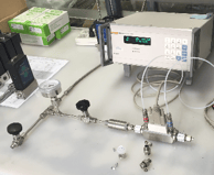
We are starting a new blog series where we will introduce you to some of the key employees here at Teledyne Hastings. Our first blog in this series will focus on our domestic sales manager, Will Harrison.

In addition to being domestic sales manager, Will works as a sales application engineer ensuring that customers select the best flow or vacuum product for their application/system. Will also works with our USA channel partners and keeps them informed of the latest products and markets for Teledyne Hastings’ products and services. Will has been with Teledyne for over thirty-five years.

 Let’s ask Will some questions to get to know him better.


  • How did you start working at Teledyne Hastings? 
    I had a close friend that worked here who mentioned the expanding sales team was looking to hire a new sales application engineer. It seemed to happen very fast … I applied, was interviewed, and was hired in less than two weeks.


  • What is a typical day like for you?
    I am always available for customer phone calls. I enjoy hearing about new opportunities or helping customers improve an existing vacuum or flow application. When not on the phone, you might find me generating a quote for a customer or helping out one of our USA sales channel partners. I also travel with our distributors as we look for new opportunities for Teledyne Hastings.


  • Let’s follow up on that, where is one of your favorite places where you have for traveled for work?
    The best place I ever traveled was Vancouver BC. Vancouver is a neat place to venture out, see the sites, and enjoy great food. Our distributor drove us up to see Whistler, which was awesome! At the time, that area had a few startup companies focused on the fuel cell industry and our mass flow meters and controllers were enjoying great success.

  • Outside of work, what is it that you like to do?
    I like to run and bike when time permits. I like to do half marathons and full marathons. I’ve even completed a full “ironman” triathlon. I also enjoy Old Dominion University (ODU) sports where I got my degree. The Lady Monarchs won back-to-back national titles in women’s basketball (1979, 1980) before the NCAA became involved. The excitement from the crowds at the ODU sporting events is great.

  • What is one part of the job that you find rewarding? 
    I enjoy working with our sales channel partners and customers to provide solutions for a wide variety of applications. I also enjoy working with my colleagues on the sales team and other members of the Teledyne Hastings Team.


In this series, we hope that every reader will be able to learn a little more about the employees they interact with here at Teledyne Hastings. If you call for support or sales, we all have a story and we would like to share that story with you.  Visit  https://info.teledyne-hi.com/blog to read more about our vacuum gauges and mass flow meters and mass flow controllers. (And look for future postings about Teledyne Hastings’ employees.)


Will MarathonWill Harrison (right) after finishing the 2022 Honolulu Marathon. Brother Glen is on the left.

To learn more about Teledyne Hastings and the products we make, visit our website or click below. 

Contact Us

Tags: Employee Spotlight

Prosperity Years 1951-1953 - Part 4 Teledyne Hastings History

Posted by The Teledyne Hastings Team on Fri, Jul 26, 2019 @ 03:17 PM

Newcomb Avenue Location 1951The early part of the 1950’s was prosperous for Hastings due in part to the demand for the Raydist and large military contracts as a result of the Korean War. Sales nearly tripled between 1950 and 1953 and there were almost 200 employees.  Hastings had outgrown its space yet again and expanded to a 14,000 square foot building on Newcomb Avenue (current day location for Teledyne Hastings).  The building was originally used as a car barn for street cars, then as a World War I armory and eventually as a manufacturing plant for ladies clothing.


With the new location, other changes were happening as well.  Hastings entered into a joint venture to supply Raydist services for the petroleum industry in the Gulf of Mexico thus creating Offshore Raydist, Incorporated. Another company was formed out of Hastings at this time, Raydist Navigation Corporation (RNC).  RNC was set up to handle the leasing of Raydist equipment outside of the Petroleum industry.


During this period, most of the focus was on Raydist and trying to establish itself in new fields.  One area was to have the Raydist on the S.S. United States.  This superliner promised to be the fastest passenger liner in the world and would serve as a troop transport in the event of war.  Because of personal relationships, Hastings could test and prove that Raydist was the superior system of conducting the tests at a measured-mile course.  The test would use a specially-designed buoy which could be cast overboard and allowed to float freely during the trials.  The relay equipment would be installed in the buoy, while the S.S. United states would carry the master station.  Raydist would then record the liner’s speed as it steamed directly toward or way from the buoy.  The tests proved to be successful and resulted in the Raydist being approved for use on the S.S. United States.  This success lead to many other shipyard opportunities for Hastings.  Within a few years, Raydist dominated the sea trial business in the United States.

S_S_United States

Raydist was also gaining momentum in the Hydrography and oil prospecting industry due to positive publicity from the Norfolk Corps of Engineers.  This publicity resulted in the first foreign Raydist sale in early 1951 to be used in charting the waters off Mozambique in southeast Africa.


During this time, Hastings completed a Raydist system for the All-Weather Flying Division of the Air Force.  It was to be used at Wright-Patterson Air Force Base in Dayton Ohio to test the accuracy of radar and other blind landing systems. Later that year, an automatic plotting board was developed to supplement the Raydist system.  The demonstration of this new product was a big event.  The board plotted a plane’s path as it performed skywriting maneuvers spelling HICO across the sky.


Manufacturers Rep Sales Mobile 1953A small percentage of Hastings business during the early 1950’s was for instrument sales.  The most important of these products were the air-meters, vacuum gauges, flow meters, accelerometers and an electronic standard cell. In order to grow this part of the business, Hastings decided to set up a manufacturer’s representative program.  By the end of 1953, Hasting’s was looking forward to seeing this manufacturer’s representative program vastly increasing instrument sales.

(Image on right is the first Manufacturer Representative's car outfitted with Hastings products.)

For more information on Teledyne Hastings be sure to visit our website www.teledyne-hi.com or contact us

Contact Us

Information for this blog was derived from “The Story of Hastings-Raydist” book by Carol Hastings Sanders 1979

Tags: Teledyne Hastings Instruments

Laying a Foundation (1947-1950)

Posted by The Teledyne Hastings Team on Fri, May 10, 2019 @ 01:22 PM

Product portfolio 1947-1By 1947, the Hastings Instrument Company could count many successful projects.  Their list of products included the following:

  • Raydist Navigation System
  • Magnetic Switch and Coil
  • Maximum Recording Accelerometer
  • Visibility Meter

While the list of projects was impressive, the company wanted to grow their profits further. Charles Hastings decided to look at his business model and make some changes.  The company needed to raise capital for further development in order to become a sizeable company. Growth would give the company the ability to attract and close larger contracts.  To do this, Hastings decided to incorporate the business and offer 3500 shares of stock.  The company charter was received from the Commonwealth of Virginia on Valentine’s Day 1947. 


Air-Meter hand lettered dial faceAfter several sales pitches and demonstrations, Hastings received two large contracts for Raydist. Along with these two contracts, the company was busy building Air-Meters for commercial sales.  Before selling the Air-Meters, the instruments needed to be calibrated.  In those early days, calibration was done by driving down the road holding a probe out the window while someone in the passenger seat held the Air-Meter.  When the car reached 5, 10, 15 etc… mph the passenger would make a note on the blank dial face and then return to the house where they would neatly letter the dial face.


first office brick distributorDuring this period of growth, Hastings realized that it was time to find a new location for the business.  By now, there were 17 people working elbow-to-elbow at the Hastings’ home and that could not continue.  The company settled on temporary location in an old brick distributorship building that had a leaky roof and flooded at spring tides, but it was at the price they could afford.

By the spring of 1948, several Raydist contracts were in the works. Air-Meters continued to sell very well, and several instruments were about to be introduced.  That same year, the Hastings Company also moved into a more permanent building for its now 75 employees, which would grow to 118 by 1950.  To secure the company and continue to make profits, Hastings realized he needed to produce a Raydist for commercial use.  The company achieved this goal in 1950 with a sale to the Norfolk Corps of Engineers for hydrographic surveys and channel dredging.2nd building Horne Brothers

By 1950, the line of Hastings Instruments increased to the following:

  • Air-Meter
  • Precision Air-Meter (for higher ranges and more accurate readings)
  • Maximum Indicating Accelerometer
  • Voltage-regulated Power Supply
  • Electronic Standard Cell
  • Vacuum Gauge

1950 product portfolioIVentimetern addition to the list of commercial instruments above, Hastings developed specialized instruments for specific customers. For example: the “Ventimeter” was used by the army to measure ventilation in clothing to keep wearers comfortable under extreme weather conditions.  The Hastings Company was now growing fast and generating handsome profits for its stakeholders.


For more information on Teledyne Hastings be sure to visit our website www.teledyne-hi.com or contact us

Contact Us

Information for this blog was derived from “The Story of Hastings-Raydist” book by Carol Hastings Sanders 1979

Register to win The History of Hastings-Raydist Book.

Tags: Teledyne Hastings Instruments

The Birth of Hastings Instruments Company (HICO) 1944-1946 (Part 2)

Posted by The Teledyne Hastings Team on Wed, Mar 13, 2019 @ 10:22 AM

Charles_Mary Hastings Home-1In September 1944, the Hastings Instrument Company started to take shape.  For quite some time, Charles & Mary conducted the business out of their home.  They received their first order in December from the Naval Aircraft Factory in Philadelphia for $800.  The order was for a rotary magnetic switch for commutating electrical circuits. 

The following month, Charles built his first heated thermopile anemometer, which he called the Air-Meter.  This Air-Meter was based on ideas he had had in 1940 for making a thermopile instrument to measure aircraft speed.  It also incorporated his invention of a way to make a thermopile compensated for both temperature and rate of change of temperature. He decided to name his radio ground speed system by combining the first syllables of the words “radio” and “distance” to form “Raydist”.

working out of homeBusiness continued to grow.  Seventeen employees would arrive at the Hastings home around 7pm on Monday, Wednesday and Friday to work on their electronic projects (see image on right).  During the day, Mary would take care of miscellaneous projects.  On one occasion, Mary agreed to have some Raydist cabinets painted by the time Charles came home.  Unfortunately, the air compressor was out of air so Mary came up with another plan.  She would take the car to the nearby service station and put as much air in the tires as she could without them bursting.  She would then drive back home, attach her paint sprayer to the tires, and paint the Raydist cabinets antennas on homeuntil her tires were almost flat.  She did this several times to complete the project before Charles came home.  The business activities took a toll on the Hastings home. The roof leaked and needed to be replaced from all the antennas mounted to it (see image on left), the driveway needed to be replaced from the damage of delivery trucks, Mary’s oven smelled like paint which caused some challenges when meal time came.

Raydist AM transmitter on helicopterIn January 1946, Hastings received their first order for a Raydist.  The Air Material Command at Wright Field in Cleveland Ohio wanted a single-dimensional Raydist system to use during aerial photography and mapping.  The final product was hand-delivered by Charles himself in October. (see image on right and below)

This Raydist order was the largest order Hastings had ever received and he felt that once they were paid for it all, their troubles would be over. 

Raydist on helicopter at Wright Airforce Base

For more information on Teledyne Hastings be sure to visit our website www.teledyne-hi.com or contact us

Contact Us

Contact Us

Information for this blog was derived from “The Story of Hastings-Raydist” book by Carol Hastings Sanders 1979

Tags: Teledyne Hastings Instruments

Before Hastings Instruments Company, the early years… (Part 1)

Posted by The Teledyne Hastings Team on Wed, Feb 13, 2019 @ 11:46 AM

charles-mary Hastings at work at NACAEver wonder where the idea or dream of Hastings originated?  Well as part 1 of our anniversary year blog posts, we thought this would be a good place to start.  Charles Hastings at the age of 10 was bitten by the radio bug and began to build and experiment with radio gear.  In 1930, at the age of 16, Charles Hastings found an opportunity to fund his experiments by fixing other people’s radios.  Many families had radios at this point, but they were very unreliable and frequently needed minor repairs.  Charles would fix radios to earn money to buy parts for his own experiments.

Soon, Charles moved on to building transmitters and enlisted the help of his high school friend, Raymond Doyle.  Their first success was when Charles spoke into a microphone and Ray heard the broadcast from his aunt’s house which was down the street. Unfortunately, the broadcast covered the entire spectrum of commercial radio broadcasting, so the entire neighborhood received the broadcast as well instead of their favorite radio programs.

After this first broadcast mishap, Hastings decided to go back to radio repair.

Charles Hastings went on to attend John Hopkins University and majored in Electrical Engineering.  Upon graduation, he was offered a position as Junior Scientific Aide with the National Advisory Committee for Aeronautics (NACA) in Hampton, Virginia. In 1939, Mary Comstock joined NACA as a mathematician and Charles was quick to ask her out for a date.  They were married within a year.

Working at NACA proved to be quite rewarding to Charles.  He came up with an idea for a magnetically operated reed switch for the spin tunnel section in order to flip the controls in its free-spinning airplane models.  This moved on to finding accurate methods to measure the speed of aircraft.  In 1940, Charles did just that, he came up with an idea for an airspeed indicator using a heated thermopile.  The idea was tested later that year at Langley Field in measuring the speed of planes.  This was the first continuous-wave heterodyne system ever used for speed measurement and was names the NACA Radio Ground Speed System.

His work continued at the NACA for a few years, but Hastings became restless and wanted to be on his own.  He felt that the work he had done with Radio Ground Speed System had more potential in the measurement of distances.  Initially Charles Hastings only wanted to create ideas for commercial products and sell the rights to others in exchange for royalties.  Hastings longtime friend James Benson was interested in being a part of this new.

Hastings Instruments Company was born in September 1944.

For more information on Teledyne Hastings be sure to visit our website www.teledyne-hi.com or contact us

Contact Us

Information for this blog was derived from “The Story of Hastings-Raydist” book by Carol Hastings Sanders 1979

Tags: Teledyne Hastings Instruments

Facts You Might Not Know about Teledyne Hastings Instruments

Posted by The Teledyne Hastings Team on Thu, May 14, 2015 @ 04:45 PM

Quality Teledyne Hastings ISO 9001 CertificationLast month, we passed our ISO 9001 surveillance audit.  It has been over twenty years since we first obtained ISO and we wanted to take a step back and review some significant accomplishments.  

Teledyne Hastings Instruments rich history and customer centric vision continues to support, influence and grow with those who depend on quality process control and automation.

That's why we wanted to take a moment and celebrate a milestone with our core clients and those considering a Teledyne Hastings Instruments Flow instrument or Vacuum Gauge for the first time.


2015_Infographic_ISO_20_Years_2

Teledyne Hastings Instruments' has been providing quality thermal mass flow instruments and vacuum meters and controllers for applications ranging from academic research to space exploration for over 70 years.  Let us work with you to find the best solution for your process.

OEM, custom applications, lead time crunch, just curious:   

Contact Us

Tags: Teledyne Hastings Instruments, Flow Controller, Flow Meter, Vacuum gauge, vacuum controllers, ISO 9001 and Thermal Mass Flow, ISO 9001 and Vacuum Gauges