Using thermal mass flow instruments by Teledyne Hastings is an easy way to quickly and accurately measure gas flow. And in some cases, a mass flow instrument may be calibrated for one gas, but then the user may want to use the instrument in another gas. In this blog, we will show how to use GCFs (Gas Conversion Factors) when using flow instruments in different gases.
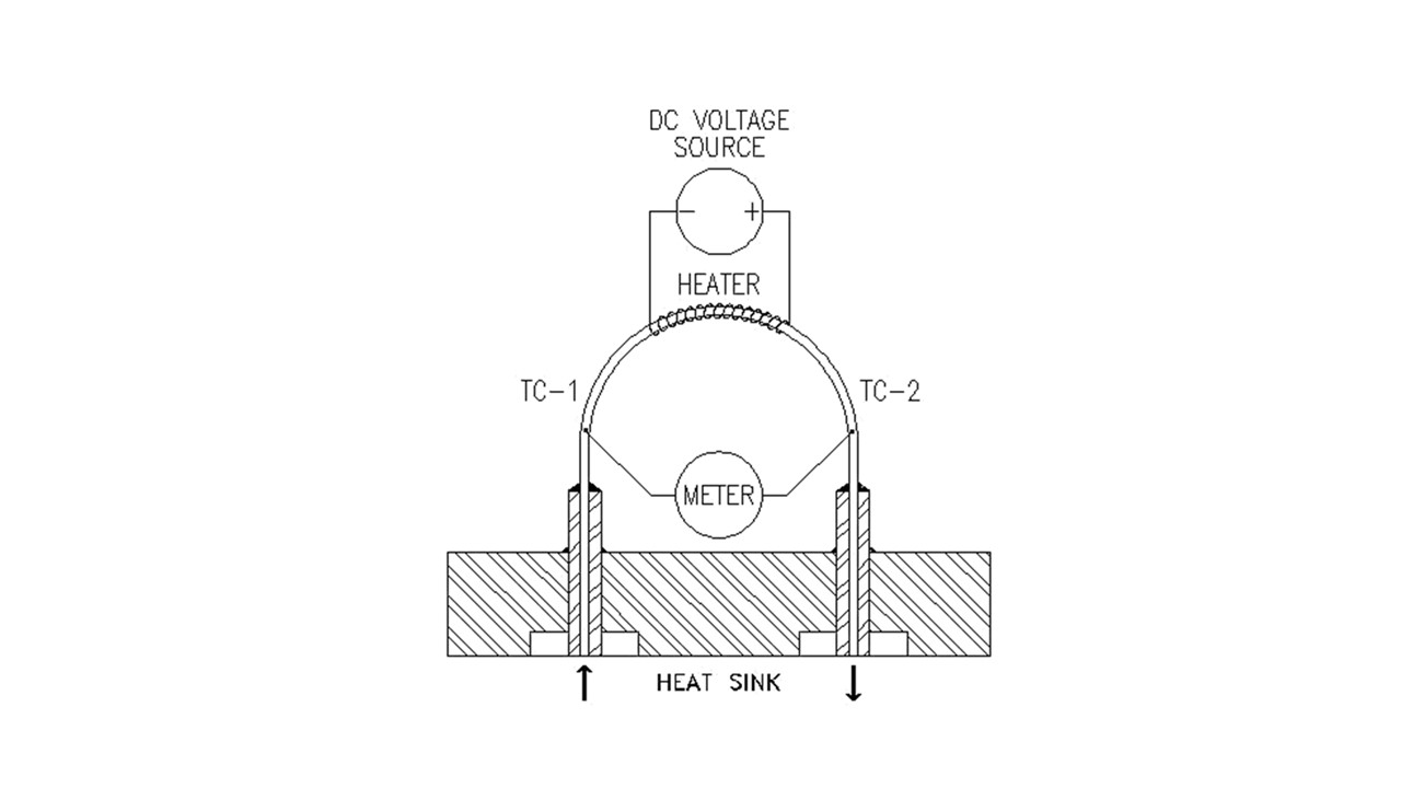
Before we get into GCFs, let’s quickly review the operation of one of our flow sensors. Below, we show a diagram of the 200 Series flow sensor. In this sensor, gas flows through a capillary tube which is heated in the middle to a temperature which is approximately 130°C. Two thermocouples, one upstream (TC-1) and one downstream (TC-2), measure the temperature. The temperature difference between the two thermocouples is proportional to the heat flow through the capillary tube. The heat flow, in turn, is proportional to the mass flow times the specific heat Cp of the gas. So, to first order, if we want to use a thermal mass flow meter that has been set up for one gas, and use it with another gas, we will multiply the output of the meter by the ratio of the specific heats. GCF ~ Cp1 / Cp2
There are a couple of things we need to point out. First, the ratio shown above is a simple approximation and does not tell the whole story. Next, the best GCFs are those that have been measured experimentally. However, in the case of dangerous gases, we use the best thermodynamic data available.
Here is a table of some common GCFs.
| Gas Conversion Factors (N2) | ||
| 200 Series | 300 Series | |
| Helium | 1.402 | 1.400 |
| Oxygen | 0.981 | 0.978 |
| Carbon Dioxide | 0.743 | 0.753 |
| Carbon Monoxide | 1.001 | 1.001 |
| Methane | 0.770 | 0.779 |
| Ammonia | 0.781 | 0.781 |
| Hydrogen | 1.009 | 1.004 |
| Argon | 1.401 | 1.405 |
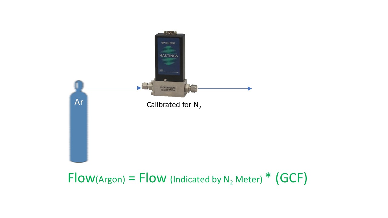
Next, we will discuss how we apply GCFs in practice. Let’s take an example of a flow meter that is calibrated for nitrogen. If we wanted to use the flowmeter in argon, we would take the output and multiply by the GCF for Argon.
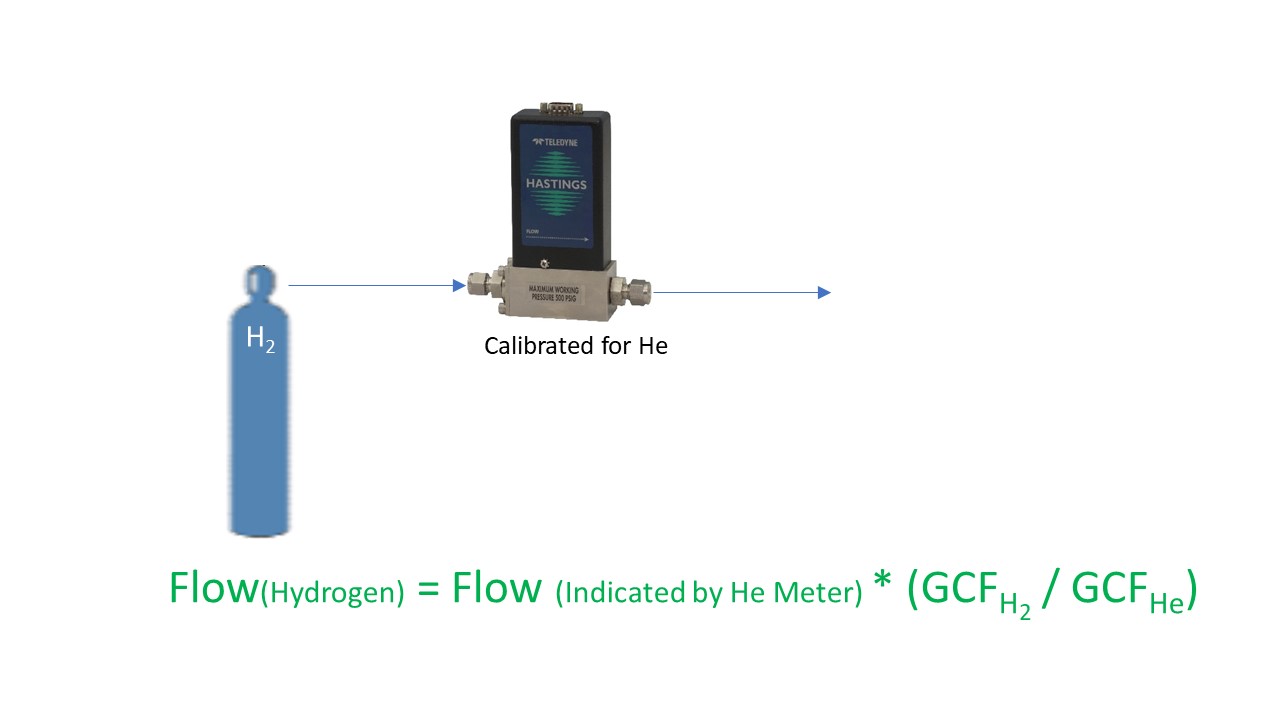
Here is another example; suppose we have a meter that is calibrated in helium and we want to use it in hydrogen. You would start by dividing the output by the GCF for helium (think of it as converting to the nitrogen equivalent), and then multiplying by the GCF for hydrogen.
Remember, always use the appropriate set of GCFs for the flow series that you are using. In other words, if you are using our Digital 300 Series, don’t apply GCFs from a 200 Series manual – they are not the same. And certainly don’t use non-Teledyne table of GCFs for use with Teledyne flow products. They might get you in the ballpark, but they will not be your best conversion.
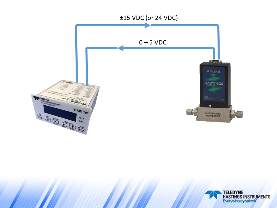
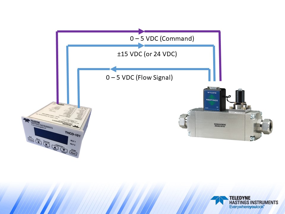
One other quick note about applying GCFs. Our line of flow power supplies, the THCD-101 (single channel) and the THCD-401 (four channel), can be used to quickly scale the analog input which is equivalent to applying a conversion factor. Let’s take another look at the Argon example. If we used the THCD-101 power supply with the nitrogen flow meter as shown below, at the nominal full scale of the flow meter, we will have a 5 VDC signal. If we want to use this same meter and power supply with Argon, we just need to “tell” the THCD-101 what value to display when it receives 5 VDC. So, if our flow meter was calibrated for nitrogen to give 5 VDC at 250 sccm, then the same flow meter will give 5 VDC in argon at 350 sccm. (250 * 1.4 = 350). So, we would then range the THCD-101 for 350 sccm. This can be done from the front panel or via the internal webserver.
Now let’s make things a little more interesting and discuss a flow controller example. Analog flow controllers work by receiving a command signal (usually 0-5 VDC, or 4-20 mA) and then they adjust their control valve such that the flow, and thus the analog signal output, matches the command signal input. (You can think of it like the cruise control in your car – you tell it you want to go 78 miles per hour, and then the engine does what it needs to do to maintain that speed). In the case of a 0-5 VDC flow controller, a 5-volt setpoint command is instructing the flow controller to set the flow to 100% of full scale. The relationship between flow rate and command signal is linear, so if the user wanted to control at 25% of full scale, then they would send a 1.25 VDC command signal (0.25 * 5 VDC = 1.25 VDC).
Now, suppose we had an HFC-202 flow controller (200 Series) that was calibrated for 200 sccm of methane and we wanted to use it to control the flow of argon. What voltage level would we need on the command signal to have a flow rate of 100 sccm of argon? Let’s first determine the full-scale flow rate (5 VDC) when using argon:
Flow (Ar) = Flow (CH4)/GCF (CH4) * GCF (Ar) = (200 sccm / 0.77) * 1.401 = 363.9
So, a 5 VDC command signal will give us 363.9 sccm of argon. If we want 100 sccm, we would send:
Command Voltage = 100 sccm (5 VDC / 363.9 sccm) = 1.374 VDC.
Now, one important note about using flow controllers in different gases. Just because we can apply GCFs does not mean that a flow controller’s valve will work properly when switching from one gas to another. As an extreme example, a flow controller valve that has an orifice sized to handle hydrogen will have a hard time handling significant flows of large polyatomic molecules like C2H6.
Teledyne flow products are easy to install and use. And our application engineers are standing by to help. We can be reached by email (hastings_instruments@teledyne.com), by phone 757-723-6531, or via LiveChat on our website www.teledyne-hi.com or by clicking the contact us button below.