Have questions? Need Help?
757.723.6531 | 800.950.2468

Teledyne Hastings Instruments Blog

Fittings for Mass Flow and Vacuum Instruments

Posted by Doug Baker on Mon, Jun 20, 2022 @ 02:48 PM

Choosing Your Fittings_Blog Social Media ImageIn this blog, we will discuss various system connections, or fittings, that are available for both our mass flow and vacuum products. We will briefly explore why you might select a particular family of fittings for your system. Also, we will touch on some basic installation Dos and Don’ts.
 

Mass Flow Meters and Mass Flow Controllers

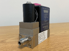
Many users of low flow (0-5 sccm up to 0-25 slm) instruments appreciate the convenience of compression fittings. The Swagelok ™ brand of compression fittings is very popular, and many users ask for these by name. Compression fittings can be very reliable; also, they can be quickly uninstalled and reinstalled as needed. And, unlike VCR ™ and VCO ™ fittings (we will talk more about these in a minute), compression fittings do not require a separate o-ring or single-use gasket. Our flow products are offered with various size Swagelok™ brand compression fittings. While the 1/4” size is the most popular for many low flow applications, we also offer, even smaller, 1/8” size as well. Metric sizes, including 10 mm and 12 mm, are also available. Then, for even higher flow applications, we also offer 1/2”, 3/4”, 1”, 1.5” and even 2” Swagelok ™ fittings. Note that the largest compression fittings require a swaging tool. (Link?)

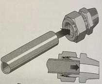
Per the “Tube Fitter’s Manual” published by Swagelok®, here are the steps for manual installation of Swagelok Tube Fittings up to 1 in. or 25 mm.

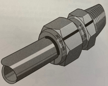
  1. Fully insert the tube into the fitting and against the shoulder; rotate the nut finger tight.

    Swagelok Tube Fitting - insert tube into fitting
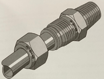
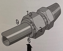
  2. Mark the nut at the 6 o’clock position.

    Swagelok Tube Fitting - mark nut at 6 oclock

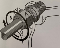
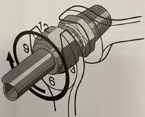
  3. While holding the fitting body steady, tighten the nut 1 ¼ turns to the 9 o’clock position.
    For 1/16, 1/8, and 3/16 in. or 2, 3, and 4 mm tube fittings, tighten the nut ¾ turn to the 3 o’clock position.

    Swagelok Tube Fitting - tighten nut

Reassembly Procedure is as follows:

  1. Prior to disassembly, mark the tubing at the back of the nut, mark a line along the nut and body flats. Use these marks to ensure that you return the nut to the previously pulled-up position.

    Swagelok Tube Fitting - mark tubing
  2. Insert the tubing or tube adapter end connection with pre-swaged ferrules into the fitting until the front ferrule seats against the fitting body.

    Swagelok Tube Fitting - insert tubing
  3. While holding the fitting body steady, rotate the nut with a wrench to the previously pulled-up position, as indicated by the marks on the tubing and flats. At this point, you will feel a significant increase in resistance. Tighten the nut slightly.

    Swagelok Tube Fitting - rotate nut

The VCR ™ system from Swagelok™ is very popular with users who need high purity, all-metal, reliable sealing for either positive pressure or vacuum applications. For these fittings, a gasket, usually metal, is used to seal between the two symmetric sealing faces. In some cases, an elastomeric or PTFE gasket can be used. Metal gaskets (e.g. copper, nickel, or stainless steel) in VCR ™ connections should only be used once. Metal gaskets can be purchased with a retainer to hold the gasket in place when installing. The gasket is secured between the mating surfaces and the nut is drawn finger tight. Then, to finish installation, two wrenches are used to tighten the connection and create the leak-free seal. Note that copper gaskets require a 1/4 turn (90°) beyond finger tight while nickel and stainless steel only require an 1/8 (45°) of a turn.

HFC-302 with VCR fittingHFC-302 with VCR fittings


Live chat

The VCO™ system is convenient when the user wants to have fast make and break connections. It is also handy when space is limited. One part of the VCO™ connection includes an o-ring while the mating connection has a flat smooth finish. Installation is easy. A nut is made finger tight and then a wrench is used to tighten by 1/8 (45°) of a turn.

Usually, your fitting selection and piping are going to be a function of the flow rate. Our application engineers are available via email, phone or LiveChat to help you.


Vacuum Gauges

There are several popular systems of connections for vacuum gauges. Selection of a system should be driven by base pressure, outgassing load, and of course, cost.

For many users who just need to reach the mTorr range of pressures, tapered pipe thread (NPT: National Pipe Tapered) connections are simple, require no external clamps or bolts, and can be assembled quickly. However, PTFE tape or some other sealant should be used on the threads for two reasons. First, the tape/sealant fills the void between the mating thread surfaces and second, the tape/sealant acts as an anti-galling lubricant between the threads.

When wrapping PTFE tape onto NPT threads, start with clean surfaces and a clean cut of the tape. Make sure the tape is flat as it is wound onto the sealing surfaces and wrap in the direction of the threads. Two to three wraps is adequate. End the wrap with a clean cut of the tape. Tighten the connection with a wrench. How tight? Well, there is no right answer except to say that you want the system to seal, but you don’t want the threads to strip. So, use a wrench until tight, but do not try to force and overtighten.

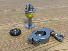
The KF system is convenient for users who need a fast leak tight system connection for their vacuum gauges. “KF” is short for Klein Flansche which is German for small flanges. Vacuum systems with KF flanges can reach into the 10-8 Torr range. KF sizes, such as KF-16 and KF-25, are related to the maximum nominal inner diameter tubing in millimeters that can be attached to the flange.

DV-6-KF-16Teledyne DV-6-KF-16 (Shown with o-ring assembly and clamp)
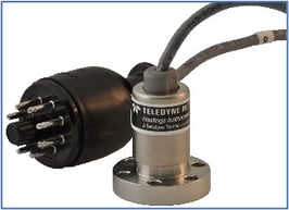
 

And lastly, ConFlat hardware is ideal for high vacuum and ultrahigh vacuum systems. ConFlat flanges have a knife-edge that seals against a gasket, usually copper. The connection is made by tightening a series of bolts; the number of bolts is a function of the size of the flange. Clean, baked, suitably pumped systems using ConFlat hardware have been known to reach pressures below 10-13 Torr.

DV-6 Gauge Tube with ConFlat FlangeDV-6 Gauge Tube with ConFlat Flange
 

If you would like to discuss your application for vacuum gauges, mass flow meters, or mass flow controllers, we are standing by. You can reach us by phone (1-800-950-2468), email (hastings_instruments@teledyne.com) , or by using our LiveChat box at www.teledyne-hi.com or clicking on the box below.

CONTACT US FOR MORE INFORMATION

Note: All photos of Swagelok fittings in this blog are used with their written permission.

Tags: mass flow controller, mass flow meter, mass flow instruments

How do I use GCF (Gas Conversion Factors) with my mass flow meter or mass flow controller?

Posted by Doug Baker on Mon, Nov 02, 2020 @ 09:54 AM

Using thermal mass flow instruments by Teledyne Hastings is an easy way to quickly and accurately measure gas flow. And in some cases, a mass flow instrument may be calibrated for one gas, but then the user may want to use the instrument in another gas. In this blog, we will show how to use GCFs (Gas Conversion Factors) when using flow instruments in different gases.

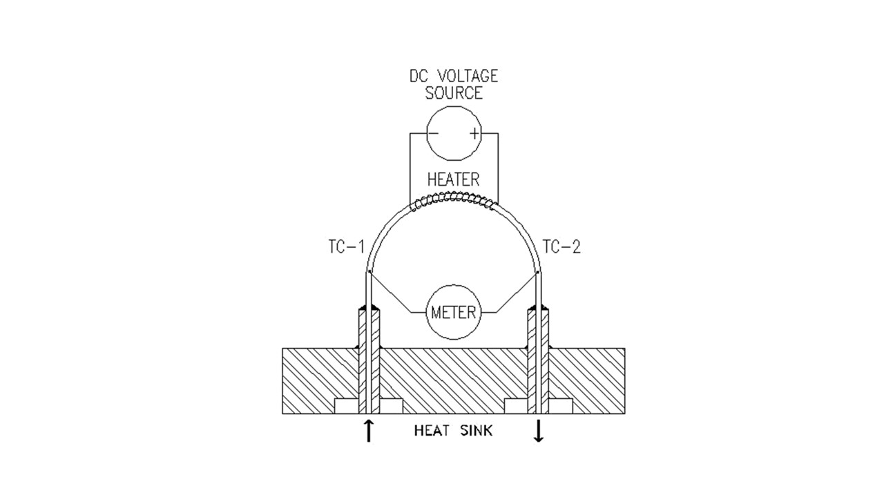
Before we get into GCFs, let’s quickly review the operation of one of our flow sensors. Below, we show a diagram of the 200 Series flow sensor. In this sensor, gas flows through a capillary tube which is heated in the middle to a temperature which is approximately 130°C. Two thermocouples, one upstream (TC-1) and one downstream (TC-2), measure the temperature. The temperature difference between the two thermocouples is proportional to the heat flow through the capillary tube. The heat flow, in turn, is proportional to the mass flow times the specific heat Cp of the gas. So, to first order, if we want to use a thermal mass flow meter that has been set up for one gas, and use it with another gas, we will multiply the output of the meter by the ratio of the specific heats. GCF ~ Cp1 / Cp2

200 Series Sensor

There are a couple of things we need to point out. First, the ratio shown above is a simple approximation and does not tell the whole story. Next, the best GCFs are those that have been measured experimentally. However, in the case of dangerous gases, we use the best thermodynamic data available.

Here is a table of some common GCFs.

Gas Conversion Factors (N2)
  200 Series 300 Series
Helium 1.402 1.400
Oxygen 0.981 0.978
Carbon Dioxide 0.743 0.753
Carbon Monoxide 1.001 1.001
Methane 0.770 0.779
Ammonia 0.781 0.781
Hydrogen 1.009 1.004
Argon 1.401 1.405

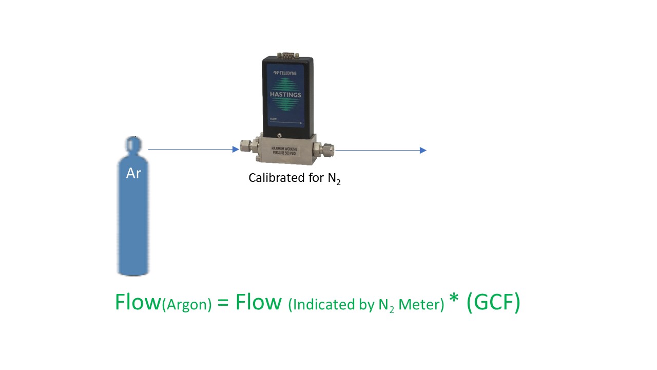
Next, we will discuss how we apply GCFs in practice. Let’s take an example of a flow meter that is calibrated for nitrogen. If we wanted to use the flowmeter in argon, we would take the output and multiply by the GCF for Argon.

Argon GCF

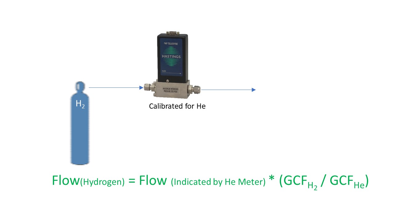
Here is another example; suppose we have a meter that is calibrated in helium and we want to use it in hydrogen. You would start by dividing the output by the GCF for helium (think of it as converting to the nitrogen equivalent), and then multiplying by the GCF for hydrogen.

H2 He GCF

Remember, always use the appropriate set of GCFs for the flow series that you are using. In other words, if you are using our Digital 300 Series, don’t apply GCFs from a 200 Series manual – they are not the same. And certainly don’t use non-Teledyne table of GCFs for use with Teledyne flow products. They might get you in the ballpark, but they will not be your best conversion.

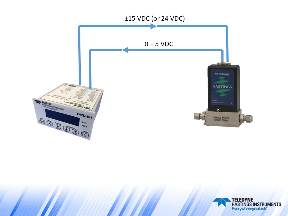
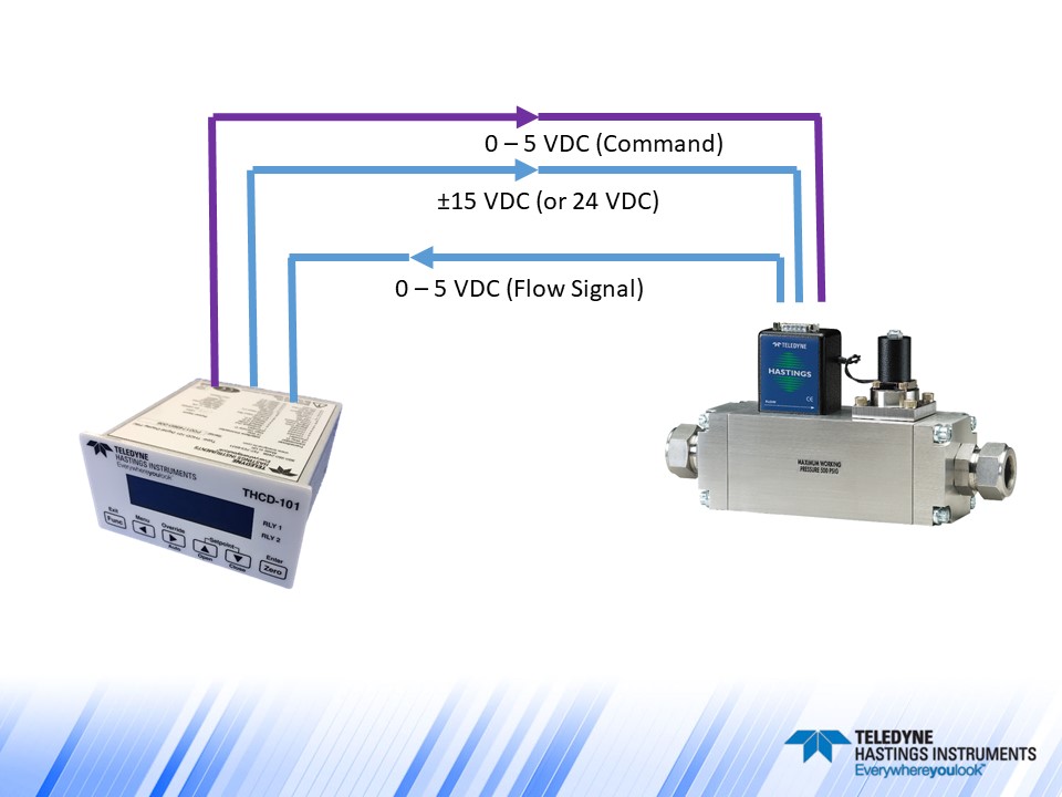
One other quick note about applying GCFs. Our line of flow power supplies, the THCD-101 (single channel) and the THCD-401 (four channel), can be used to quickly scale the analog input which is equivalent to applying a conversion factor. Let’s take another look at the Argon example. If we used the THCD-101 power supply with the nitrogen flow meter as shown below, at the nominal full scale of the flow meter, we will have a 5 VDC signal. If we want to use this same meter and power supply with Argon, we just need to “tell” the THCD-101 what value to display when it receives 5 VDC. So, if our flow meter was calibrated for nitrogen to give 5 VDC at 250 sccm, then the same flow meter will give 5 VDC in argon at 350 sccm. (250 * 1.4 = 350). So, we would then range the THCD-101 for 350 sccm. This can be done from the front panel or via the internal webserver.   

HFM200 with THCD

Now let’s make things a little more interesting and discuss a flow controller example. Analog flow controllers work by receiving a command signal (usually 0-5 VDC, or 4-20 mA) and then they adjust their control valve such that the flow, and thus the analog signal output, matches the command signal input. (You can think of it like the cruise control in your car – you tell it you want to go 78 miles per hour, and then the engine does what it needs to do to maintain that speed). In the case of a 0-5 VDC flow controller, a 5-volt setpoint command is instructing the flow controller to set the flow to 100% of full scale. The relationship between flow rate and command signal is linear, so if the user wanted to control at 25% of full scale, then they would send a 1.25 VDC command signal (0.25 * 5 VDC = 1.25 VDC).

HFC with THCD

Now, suppose we had an HFC-202 flow controller (200 Series) that was calibrated for 200 sccm of methane and we wanted to use it to control the flow of argon. What voltage level would we need on the command signal to have a flow rate of 100 sccm of argon? Let’s first determine the full-scale flow rate (5 VDC) when using argon:

Flow (Ar) = Flow (CH4)/GCF (CH4) * GCF (Ar) = (200 sccm / 0.77) * 1.401 = 363.9

So, a 5 VDC command signal will give us 363.9 sccm of argon. If we want 100 sccm, we would send:

Command Voltage = 100 sccm (5 VDC / 363.9 sccm) = 1.374 VDC.

Now, one important note about using flow controllers in different gases. Just because we can apply GCFs does not mean that a flow controller’s valve will work properly when switching from one gas to another. As an extreme example, a flow controller valve that has an orifice sized to handle hydrogen will have a hard time handling significant flows of large polyatomic molecules like C2H6.

Teledyne flow products are easy to install and use. And our application engineers are standing by to help. We can be reached by email (hastings_instruments@teledyne.com), by phone 757-723-6531, or via LiveChat on our website www.teledyne-hi.com or by clicking the contact us button below.

Contact Us

Tags: Flow Meter, mass flow conversion, mass flow controller, mass flow meter, Gas Conversion

FAQ Corner – Specifying range, pressures on Mass Flow Instruments

Posted by Wayne Lewey on Wed, May 29, 2013 @ 10:01 AM

We often see the label “One Size Fits All”.  This may be fine for some consumer goods.  However, it can be quite problematic when applied to items like shirts, gloves, or even golf clubs.  “One Size Fits All” also does not work for Mass Flow Controllers (MFC).  Not all applications are alike.  Forcing a “One Size Fits All” MFC into an unsuitable application can squander accuracy and induce valve failure.

Why do you need to specify the gas flow range on a MFC?  The Full Scale (FS) Range and Gas on a MFC directly correlates to the transmitted output (analog or digital) of the device.  In an analog device, the maximum output value (such as 5 vdc or 20 mA) will be equivalent to the FS value.  The accuracy of most MFCs is a function of this FS Range.  For analog devices, it is commonly ±1% of FS.  For digital devices, it is commonly published to be ±(0.5% of Reading + 0.2% FS).  Selecting the FS Range close to an application’s maximum flow rate optimizes accuracy for that specific application.  This is a good practice.  In addition, the gas must be specified.  Most MFCs use thermal based sensors.  These sensors actually measure the molecular flow rate rather than the mass flow rate.  Various gas molecules transfer heat differently, and thus the gas must be known.

Why do you need to specify Upstream Pressure and Downstream Pressure on a MFC?  Again, not all applications are the same.  A “One Size Fits All” MFC is typically not set up for applications at high pressure, low pressure, high differential pressure, or low differential pressure.  The definition of high and low will also fluctuate from one user to another.  Teledyne Hastings Instruments selects and tests MFC valve components (orifice, spring, etc.) that optimize valve stability for the exact application pressure conditions.When using a Teledyne Hastings Instruments MFC, you will always find the FS Range / Gas and the Upstream / Downstream Pressures listed on the serial number label.

Sample Calibration Sticker for MFC


Wayne Lewey was first exposed to mass flow controllers while an undergraduate at North Carolina State University (Chemical Engineering).  Today, Wayne is the International Sales Manager at Teledyne Hastings Instruments and can be reached at wlewey@teledyne.com.

Tags: Teledyne Hastings Instruments, Flow Controller, Gas Flow Range, pressure, range, differential pressure, mass flow controller, mass flow meter