Note: The content of this blog was updated February 4, 2023 to provide more information for the reader.
The applications engineers here at Teledyne Hastings discussed topics for our blog. We all agreed that one of the more frequent questions fielded, involves the units used to measure vacuum levels. We find that the technicians who use their vacuum system daily often seem to develop a sixth sense about the “health” of their systems. They know something isn’t quite right when the base vacuum pressure (or rate of pressure change) is not what they expect. So, when vacuum pressure measurements are inconsistent from batch-to-batch, that is the time when the user stops to ask the meaning behind the data that their vacuum measurement instrumentation is providing.
Measuring Vacuum Pressures
A vacuum exists when there is negative pressure, or when there is system pressure that is less than atmospheric pressure. Manufacturing processes generate different levels of vacuum when operating at peak efficiency for a given vacuum application that are measured using a vacuum gauge. Absolute vacuum is the absence of all matter. Atmospheric pressure, also known as barometric pressure, is the pressure due to earth’s atmosphere. Atmospheric pressure is 760 Torr or 14.696 psia at sea level and changes with altitude. The vacuum pressure scale is book-ended by absolute vacuum pressure in the “ultra-high” vacuum range and atmospheric pressure at the “rough” vacuum range. It should be noted that absolute vacuum, or perfect vacuum, is never truly attained.
Most users know that vacuum is commonly measured using units of pressure. There are a few different systems of pressure measurement, and this blog will discuss those most used. In Armand Berman’s book, Total Pressure Measurements in Vacuum Technology, pressure unit systems are divided into two categories: “Coherent Systems” and “Other Systems”.
Common Units of Vacuum
“Coherent Systems” of units are based on the definition of pressure (P) as the force (F) exerted on a chamber wall per unit area (A). P = F/A. The International System of Units, or SI units, is commonly used for pressure measurement. http://physics.nist.gov/cuu/Units/units.html The SI unit for pressure is the Pascal (Pa), and it is interesting to note that NIST (National Institute of Standards and Technology) published papers are always required to use SI units. Again, the SI unit for pressure (force per unit area) is the Pascal. 1 Pa = 1 N /m2.
As a unit of pressure, the Pascal is not always convenient to use because vacuum systems often operate in pressure ranges where collected data results in large numbers. For example, near atmospheric pressure, we would measure approximately 100,000 Pa. So, a more convenient unit, the bar, was developed. (1 bar = 100,000 Pa)
Moving lower in pressure, it is very helpful to then use the mbar (1 mbar = 0.001 bar), which has become the predominate unit of measure in Europe, as the basis for describing pressure levels. As a specific example, look at the base pressure specification of a turbo pump, which will typically be given in terms of mbar (e.g., Base Pressure < 1 x 10⁻¹⁰ mbar).
“Other Systems” of units include the Torricelli system, which is based on an experiment (shown in the diagram below) conducted by the Italian scientist, Evangelista Torricelli. In this experiment, the pressure exerted on the mercury can be shown to be P = hdg, where h is the height of the mercury column, d is the density, and g is the acceleration due to gravity.

By measuring the mercury column height, the pressure can be determined. The Torr unit (named after Torricelli) has been defined as 1 millimeter of mercury (1 Torr = 1 mmHg). This unit, as well as the use of the mTorr unit (1 mTorr = 0.001 Torr), is commonly used in the United States. Historically, pressure was sometimes described in terms of “microns”, which simply meant a mercury column height of one micron (1x10⁻⁶ m). Note that the micron and the mTorr are the same.
Lastly, it should be noted that occasional confusion arises between the use of different, but seemingly similar, units of pressure. As explained above, the mbar and the mTorr are not the same. One mbar has the same order of magnitude as one Torr (1 mbar = 0.75 Torr).
Unit Conversions
The table below gives some conversion values between various commonly used units of pressure and vacuum. A useful website for conversions:
http://www.onlineconversion.com/pressure.htm
| |
Pa
|
mbar
|
Torr
|
mTorr (micron)
|
Atm
|
|
1 Pa =
|
1
|
0.01
|
0.0075
|
7.50
|
~ 10-5
|
|
1 mbar =
|
100
|
1
|
-.75
|
750.06
|
~ 10-3
|
|
1 Torr =
|
133.3
|
1.333
|
1
|
1000.0
|
~ 10-3
|
|
1 mTorr (micron) =
|
0.1333
|
0.00133
|
0.001
|
1
|
~ 10-6
|
|
1 Atm =
|
101,325
|
1013.25
|
760
|
760,000
|
1
|
Absolute Pressure and Gauge Pressure
In conclusion, keep in mind that vacuum measurements can be referenced to ambient pressure, gauge pressure measurement or absolute pressure measurement (perfect vacuum). An absolute pressure measurement is referenced with respect to absolute vacuum. Absolute pressure will often be designated by the letter “a” after the unit of measure; “psia.” As an example, an absolute pressure reading of 30 psia (pounds per square inch absolute) is a pressure that is 30 psi above vacuum. It is important to understand that there is no negative absolute pressure. There are some
Gauge pressure measurements are measured relative to the ambient atmospheric pressure. Relative, or gauge pressure, will often be designated by the letter “g” after the unit of measure; “psig.” As an example, 30 psig is a gauge pressure that is 30 psi above ambient atmosphere (typically 14.7 psia at sea level). In this example the gauge pressure, 30 psig, is equal to an absolute pressure of 44.7 psia.
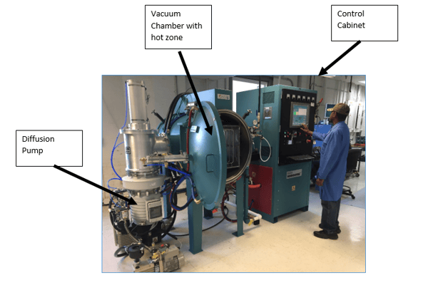
What is a vacuum system?
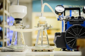
A vacuum system can consist of multiple a vacuum pumps and vacuum gauges attached to a tank that is designed to measure below atmospheric pressure. The vacuum pumps reduce the air pressure inside of the tank to the pressure range that the vacuum pump is rated for. Different vacuum pumps bring the vacuum pressure to different levels depending on the strength of the vacuum pump.
Attached to the tank is usually at least one vacuum pressure gauge. An application may require another type of vacuum gauge to measure a different pressure point. An example of this would be using a piezo pressure gauge and a Pirani pressure gauge to have a larger range of the vacuum pressure measured. A piezo vacuum gauge would be used to measure the rough vacuum range around atmosphere and the Pirani could be used to measure below 1 Torr in the mTorr range. There are vacuum gauges that use technologies from different vacuum gauges to create a combination vacuum gauge to measure vacuum pressure across a wider pressure range. Teledyne Hastings combines both the Pirani and piezo technologies to make the HVG-2020B vacuum pressure gauge.
Vacuum Gauges Poster
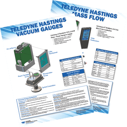 |
Vacuum Gauges
Free Poster
Unit Conversions and More

|
Original Content posted Sept 22, 2014
FAQ Corner - Units for Vacuum Measurement
an overview of units used to measure pressure
Earlier this year, the applications engineers here at Teledyne Hastings discussed topics for our blog. We all agreed that one of the more frequent questions that we discuss with folks involve the units used to measure vacuum levels. We find the technicians who use their vacuum systems daily often seem to develop a sixth sense about the “health” of their systems. They know something isn’t quite right when the base pressure (or rate of pressure change) is not what they expect. So, when pressure measurements are not consistent from batch to batch, that is the time when the user stops to ask the meaning behind the data that their vacuum measurement instrumentation is providing.
Now, most users know that vacuum is commonly measured using units of pressure. There are a few different sets of pressure units, and this blog will discuss the more commonly used ones. In Armand Berman’s book, Total Pressure Measurements in Vacuum Technology, pressure unit systems are divided into two categories: “Coherent Systems” and “Other Systems”.
Coherent Systems of Units are based on the definition of pressure (P) as the force (F) exerted on a chamber wall per unit area (A). P = F/A. The International System of Units, or SI units, is commonly used for pressure measurement. http://physics.nist.gov/cuu/Units/units.html The SI unit for pressure is the Pascal (Pa). It interesting to note that at NIST (National Institute of Standards and Technology), published papers are always required to use the SI set of units. Again, the SI unit for pressure (force per unit area) is the Pascal. 1 Pa = 1 N /m2.
Now, the Pascal as a unit of pressure is not always the most convenient because vacuum systems are often operating in a range of pressures where we would need to collect data using large numbers. For example, near atmospheric pressure, we would measure approximately 100,000 Pa. So, a more convenient unit, the bar, has been derived. (1 bar = 100,000 Pa)
Moving lower in pressure, it is very helpful to then use the mbar (1 mbar = 0.001 bar). So many vacuum users, especially in Europe, use the mbar as the basis for describing pressure levels. As a specific example, look at the base pressure specification of a turbo pump, it will be given in terms of mbar (e.g. Base Pressure < 1 x 10⁻¹⁰ mbar).
Another system of pressure units is based on the Torricelli experiment (shown in the diagram). In this experiment, the pressure exerted on the mercury can be shown to be P = hdg, where h is the height of the mercury column, d is the density, and g is the acceleration due to gravity.
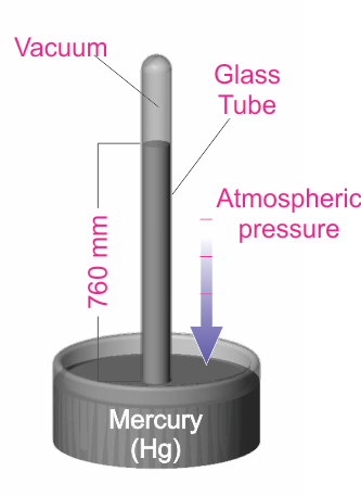
By measuring the mercury column height, the user can determine the pressure. The Torr unit (named for the Italian scientist Torricelli) has been defined to be 1 millimeter of mercury (1 Torr = 1 mmHg). This unit is very common, especially in the United States. It is also common to use the mTorr (1 mTorr = 0.001 Torr). Many years ago, pressure was sometimes described in terms of “microns”, which simply meant a mercury column height of one micron (1x10⁻⁶ m). Note that the micron and the mTorr are the same.
One last word about the units used to measure vacuum: on occasion, there is confusion between pressure units. As we have seen above, the mbar and the mTorr are not the same. One mbar has the same order of magnitude as one Torr (1 mbar ≈ 0.75 Torr). The table below gives some approximate conversion values. A useful website for conversions:
http://www.onlineconversion.com/pressure.htm
|
|
Pa
|
mbar
|
Torr
|
mTorr (micron)
|
Atm
|
|
1 Pa =
|
1
|
0.01
|
0.0075
|
7.50
|
~ 10-5
|
|
1 mbar =
|
100
|
1
|
0.75
|
750.06
|
~ 10-3
|
|
1 Torr =
|
133.3
|
1.333
|
1
|
1000.0
|
~ 10-3
|
|
1 mTorr (micron) =
|
0.1333
|
0.00133
|
0.001
|
1
|
~ 10-6
|
|
1 Atm =
|
101,325
|
1013.25
|
760
|
760,000
|
1
|
Douglas Baker is the Director of Sales & Business Development of Teledyne Hastings. Antonio Araiza prepared the Torricelli experiment drawing. Antonio is the head of Technical Documentation at Teledyne Hastings (and is among the best soccer referees in the Commonwealth of Virginia).

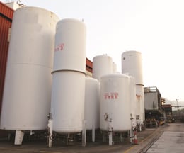
 n cryogenic applications, especially those mounted on trucks, railcars, and ISO containers, vessels face some of the harshest mechanical and environmental conditions in industry. Because these tanks are in motion, often over uneven terrain or long rail routes, the vacuum sensor must be reliable and remain accurate despite constant vibration. Vibration, shock, temperature swings, and outdoor exposure all place immense demands on sensors tasked with delivering reliable vacuum measurements.

 Rugged stainless steel housing built for outdoor environments
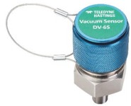
 The Teledyne Hastings Instruments’ DV-6S stands out as a purpose engineered solution for mobile cryogenic vessels. It’s the go-to vacuum sensor for LNG fuel tanks on gas powered trucks. With its extreme shock and vibration performance, rugged outdoor ready design, and precise vacuum measurement capabilities, it delivers reliability in environments where other sensors fail.
 Most people are aware that the HVG-2020B wide range vacuum gauge has an optional display, but not everyone realizes that it's much more than just a display. It's actually a color touchscreen display and is packed with features. Let's take a look.


 There are numerous, diverse vacuum applications and different vacuum systems can require specific thermocouple vacuum gauge tubes. At the most basic level, vacuum systems can be installed in a variety of environments including outdoor with exposure to weather elements, indoor industrial and laboratory conditions in which exceptionally high cleanliness standards are required.
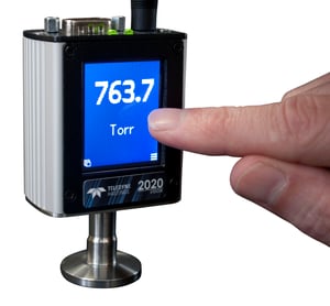 We at Teledyne Hastings Instruments are pleased to introduce the newest member of our vacuum measurement portfolio, the HVG-2020A. The HVG-2020A is a piezoresistive vacuum sensor with an optional touchscreen display that reads from 0.1-1000 Torr. The sensor uses 316 Stainless Steel as the wetted material and provides a gas independent pressure measurement, meaning your measurement will be accurate no matter what gas species is being used. The HVG-2020A features an excellent accuracy rating of ±(0.1% of Reading + 0.5 Torr). This rugged sensor comes in a number of system connections for ease of installation: 1/8” NPT, 1/4” VCR®, 1.33” Mini-CF, 2.75” CF, KF-16, KF-25, 1/2” Weld Stub, and 1/2” VCR. Let’s talk about some of the powerful features that allows the HVG-2020A to stand out.
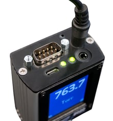 Analog I/O: The HVG-2020A has a 9 pin D-sub connector on top of the assembly that allows an analog output signal to be measured amongst other features. The selected linear analog output signal is proportional to the full scale range of the sensor (1000 Torr). Available outputs are 0-1 VDC, 0-5 VDC, 0-10 VDC, 0-20 mA, and 4-20 mA. The sensor will come configured from the factory with one of these outputs active, but can be easily changed by the user should output requirements change. Through the touchscreen display, there is a menu that allows the user to cycle through the available output options. If the HVG-2020A was configured without a touchscreen, the analog output can be changed via digital communications, which we’ll talk about in the next section. In addition to the analog output, the 9 pin D-sub will have Hi & Lo set points. The Hi set point is active when the pressure is above the set value and the Lo set point is active when the pressure is below the set value. Finally, the 9 pin D-sub has a pin for input power. The HVG-2020A can accept 12-36 VDC for power. In the event, the user doesn’t have 12-36 VDC to send via the 9 pin D-sub, there’s a 24 VDC input connection port that’s compatible with a bayonet-style power supply.
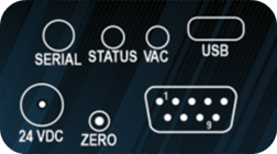 Digital I/O: As mentioned earlier, the HVG-2020A has a few different methods digital communication can be established. First and easiest is the micro-USB port on top of the gauge. This will allow the instrument to be directly connected to a computer without the need for adapters or extra wiring. There is also a 4-conductor TRRS jack on top of the instrument. This port can be used for daisy-chaining gauges together with RS485 or a standard RS232 communication connection. Finally, the 9 pin D-sub will have two pins designated for TTL serial communication. These digital communications (with the exception of TTL) can be connected to a PC and used with our Free Windows software for the HVG-2020A. The software has a number of features including data logging and customization/configuration of the gauge. Digital communication also allows for command syntax to be sent manually to the instrument. These commands are especially important if the HVG-2020A was ordered without a touchscreen display. Through digital communication, the user can issue commands that change the analog output, adjust set point values, stream pressure readings, or change pressure units, just to name a few.
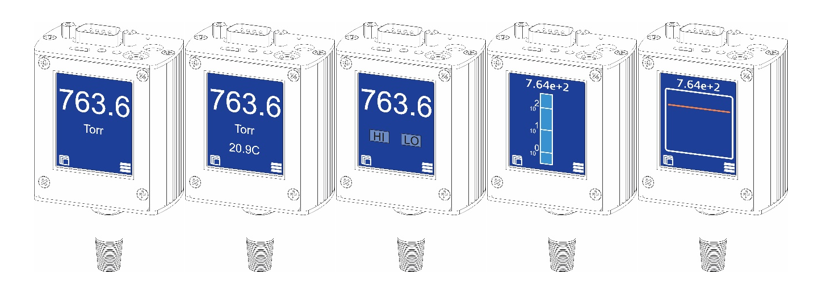
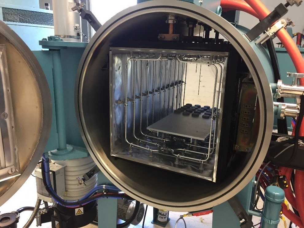 Inside the hot zone. Note the series of Molybdenum rod elements.