How Teledyne Hastings Mass Flow Meters Ensure Aircraft Safety

Every day, the skies are busy – approximately 100,000 flights take off and land globally, moving passengers and cargo across continents with remarkable consistency. With this volume of daily air travel, the integrity of every aircraft component is non-negotiable. Even the smallest leak can compromise performance, safety or efficiency.
This is where Teledyne Hastings Instruments (THI) plays a pivotal role. THI offers a range of product families, widely used in aviation leak testing, that help ensure that essential aircraft systems remain tight, reliable and ready for flight by supporting aviation manufacturers and the maintenance, repair and overhaul (MRO) teams as they maintain the highest standards of quality and performance.
Why Leak Testing Matters in Aviation
A standard process of the manufacturing and maintenance of nearly every major aircraft system includes leak testing and/or performance testing. Some key aircraft components that are commonly leak-tested include: 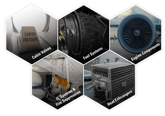
-
Cabin & Fuselage Pressurization Systems (Cabin Valves)
Ensure the aircraft can maintain safe cabin pressure throughout all phases of flight.
-
Fuel Systems
Detects leakage in lines, valves and components that must remain airtight to prevent safety hazards.
-
Engine Components
Verifies integrity of fuel manifolds, nozzles and lines; high-pressure bleed air systems (ducts, couplings); oil system components.
-
Oxygen Systems & Fire Suppression Lines
Ensures critical safety systems are fully sealed, reliable and mission-ready
-
Heat Exchangers
Verifies performance and integrity of heat exchangers to manage thermal loads in engines, cabin environment control systems (ECS), hydraulic systems and avionics.
Where Teledyne Hastings Fits In
For these applications, THI provides their line of thermal mass flow meters. These provide accuracy, speed and repeatability – key advantages for both production environments and high-throughput test standards.
Flow Meters Used in Leak Testing
Teledyne Hastings offers three (3) primary product families widely used in aviation leak testing. These flow meters are selected based on the required flow range, speed and sensitivity for the specific test application.
200 Series
Rugged general-purpose thermal mass flow meters
The 200 Series is known in the industry for its stable output and reliable repeatability. Also, the 200 Series with Laminar Flow Element (HFM-200-LFE) can measure large flow rates with remarkably low pressure drops.
300 Series
Fast response for dynamic testing
The 300 Series has an extremely fast response time – the sensor has a response time of 300 milliseconds. It also has fold-over protection which prevents large over-ranged leaks from being confused with on-scale values.
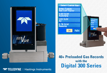
Digital 300 Series
Fast response with higher accuracy
The Digital 300 Series offers the same features as the 300 Series, but it also features improved accuracy and additional features, such as optional local touchscreen display and IP-67 enclosure.
Each of these product families are available in four (4) Full-Scale (FS) Range sizes, enabling coverage across most aviation leak-test applications and/or performance tests.
|
Low Flow
0-5 sccm to 0-25 SLM
|
Medium Flow
0-25 SLM to 0-1,000 SLM
|
High Flow
0-1,000 SLM to 0-2,500 SLM
|
Ultra-High Flow
0-2,500 SLM to 15,000 SLM
|
What Happens During Aviation Leak Tests?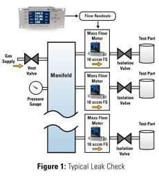
A typical leak test is shown in Figure 1. For high throughput leak detection, a pressurized manifold has multiple connections for mass flow meters. On the outlet side of each flow meter is an isolation valve and the test part. When the isolation valve is opened, the test part leaks will be noted by the movement of clean dry air across the flow meter. The test part is only exposed to clean dry air. Leak detection with mass flow meters is faster than alternative methods like pressure decay testing and helium leak detectors. It is also cleaner than hydrotesting, bubble testing and liquid penetrate testing.
Confidence at 40,000 Feet
With tens of thousands of aircraft in the air each day, you can fly confidently knowing that Teledyne Hastings Instruments helps keep critical aviation components safe, sealed and flight ready. Our mass flow meters provide the precision, speed and reliability manufacturers and MRO teams depend on.
Beyond performance, Teledyne Hastings products are built for long term stability, making them a trusted choice for high-throughput production environments and demanding aerospace applications. As aircraft systems grow more advanced and global flight activity continues to increase, Teledyne Hastings Instruments remains committed to supporting the aviation industry with measurement solutions engineered for safety, consistency and total peace of mind.
Visit https://www.teledyne-hi.com/en-us/what-we-do/thermal-mass-flow to learn more about THI's Mass Flow Meters.
If you have questions about mass flow meters, feel free to contact us by phone (+1-757-723-6531 or 1-800-950-2468), email Hastings_Instruments@Teledyne.com, or via Live Chat on our website www.teledyne-hi.com.

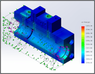
 n cryogenic applications, especially those mounted on trucks, railcars, and ISO containers, vessels face some of the harshest mechanical and environmental conditions in industry. Because these tanks are in motion, often over uneven terrain or long rail routes, the vacuum sensor must be reliable and remain accurate despite constant vibration. Vibration, shock, temperature swings, and outdoor exposure all place immense demands on sensors tasked with delivering reliable vacuum measurements.

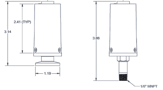
 Rugged stainless steel housing built for outdoor environments
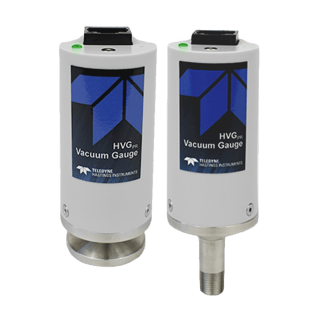
 The Teledyne Hastings Instruments’ DV-6S stands out as a purpose engineered solution for mobile cryogenic vessels. It’s the go-to vacuum sensor for LNG fuel tanks on gas powered trucks. With its extreme shock and vibration performance, rugged outdoor ready design, and precise vacuum measurement capabilities, it delivers reliability in environments where other sensors fail.


 InfoRAD Corp. was a part of Applied Engineering which became a distributor for Teledyne Hastings Instruments in 1983. Applied Engineering decided to spin-off InfoRAD in 2003, and InfoRAD immediately began the transition from a pure sales office to a complete sales, calibration, repair, and custom system design facility. They support customers across South Korea from their headquarters in the M-City Tower in Goyang. The office sits on Seoul’s northwest edge which is only 30 minutes to downtown Seoul and about 40 minutes to Incheon International Airport via expressway or airport rail. This convenient location facilitates fast deliveries, quick on-site visits, and smooth travel for visiting engineers. InfoRAD stocks vacuum gauges, vacuum transducers, mass flow meters (MFMs), and mass flow controllers (MFCs). This means you don’t have to wait for long overseas shipments.


 The last component to Chell’s success (and the topic of this blog) is their extensive calibration lab. Chell operates a complete calibration and repair lab capable of servicing instruments that measure Flow (Gas), Vacuum, Pressure, Temperature, and Electrical properties. Chell’s lab is UKAS accredited (fully accredited to ISO/IEC17025:2017). Chell can calibrate and repair nearly all Teledyne Hastings Instruments vacuum gauges, mass flow meters, and mass flow controllers. They also stock spare parts in England to quickly support most mass flow meter and mass flow controller repairs.