 We are starting a new blog series where we will introduce you to some of the key employees here at Teledyne Hastings. Our first blog in this series will focus on our domestic sales manager, Will Harrison.
In addition to being domestic sales manager, Will works as a sales application engineer ensuring that customers select the best flow or vacuum product for their application/system. Will also works with our USA channel partners and keeps them informed of the latest products and markets for Teledyne Hastings’ products and services. Will has been with Teledyne for over thirty-five years.
Let’s ask Will some questions to get to know him better.
- How did you start working at Teledyne Hastings?
I had a close friend that worked here who mentioned the expanding sales team was looking to hire a new sales application engineer. It seemed to happen very fast … I applied, was interviewed, and was hired in less than two weeks.
- What is a typical day like for you?
I am always available for customer phone calls. I enjoy hearing about new opportunities or helping customers improve an existing vacuum or flow application. When not on the phone, you might find me generating a quote for a customer or helping out one of our USA sales channel partners. I also travel with our distributors as we look for new opportunities for Teledyne Hastings.
- Let’s follow up on that, where is one of your favorite places where you have for traveled for work?
The best place I ever traveled was Vancouver BC. Vancouver is a neat place to venture out, see the sites, and enjoy great food. Our distributor drove us up to see Whistler, which was awesome! At the time, that area had a few startup companies focused on the fuel cell industry and our mass flow meters and controllers were enjoying great success.
- Outside of work, what is it that you like to do?
I like to run and bike when time permits. I like to do half marathons and full marathons. I’ve even completed a full “ironman” triathlon. I also enjoy Old Dominion University (ODU) sports where I got my degree. The Lady Monarchs won back-to-back national titles in women’s basketball (1979, 1980) before the NCAA became involved. The excitement from the crowds at the ODU sporting events is great.
- What is one part of the job that you find rewarding?
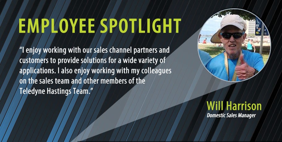
I enjoy working with our sales channel partners and customers to provide solutions for a wide variety of applications. I also enjoy working with my colleagues on the sales team and other members of the Teledyne Hastings Team.
In this series, we hope that every reader will be able to learn a little more about the employees they interact with here at Teledyne Hastings. If you call for support or sales, we all have a story and we would like to share that story with you. Visit https://info.teledyne-hi.com/blog to read more about our vacuum gauges and mass flow meters and mass flow controllers. (And look for future postings about Teledyne Hastings’ employees.)
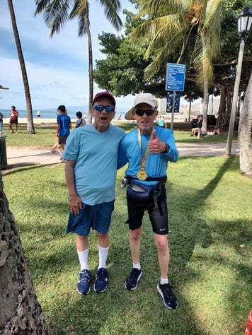 Will Harrison (right) after finishing the 2022 Honolulu Marathon. Brother Glen is on the left.
To learn more about Teledyne Hastings and the products we make, visit our website or click below.

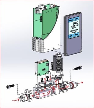
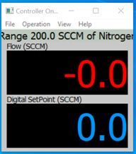
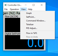
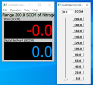
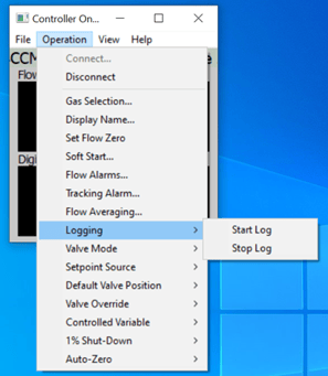
 Teledyne Hastings has a broad offering of thermal mass flow meters, mass flow controllers, and vacuum instruments. Within each of our digital product families, we offer both analog output (e.g. 0-5 VDC, 0-10 VDC, and 4-20 mA) and digital outputs (RS232, RS485, and USB). Typically, our customers will interface our instruments to their data acquisition systems. But, in some cases, our users want a fast and easy method to configure, control, and collect data with our instruments. In this blog, we will discuss our Windows-based programs. Specifically, we will answer three questions:
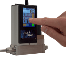 What do our Windows-based interface programs do?
 and then clicking on Connect
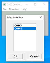
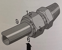
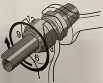
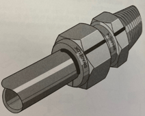
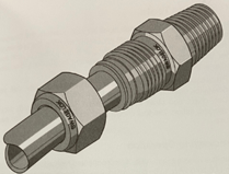
 In this blog, we will discuss various system connections, or fittings, that are available for both our mass flow and vacuum products. We will briefly explore why you might select a particular family of fittings for your system. Also, we will touch on some basic installation Dos and Don’ts.
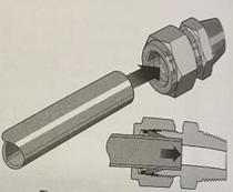
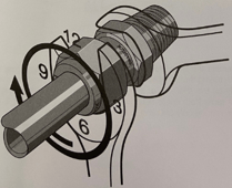
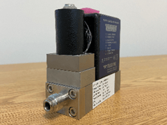 HFC-302 with VCR fittings
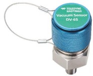
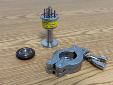 Teledyne DV-6-KF-16 (Shown with o-ring assembly and clamp)
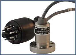 DV-6 Gauge Tube with ConFlat Flange
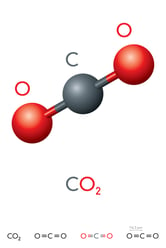
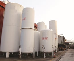
 This blog is the next installment in a series focusing on industrial gases. The first blog featured SF6 and can be found here:

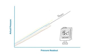
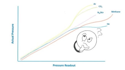
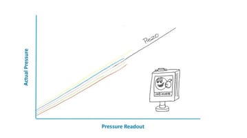
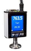
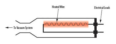 A Pirani vacuum gauge contains a heated component, such as a wire or thin-film membrane (see figure on right), which is brought to an elevated temperature, typically through the use of a bridge circuit. As changes in gas molecular density occur, the transfer of heat from the wire to the gas is affected. This heat loss is dependent on gas type and pressure, and the amount of energy required to keep the wire at temperature varies accordingly. Consequently, the amount of energy is dependent on vacuum pressure and can be converted to a pressure value.
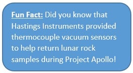

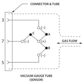

 There are numerous, diverse vacuum applications and different vacuum systems can require specific thermocouple vacuum gauge tubes. At the most basic level, vacuum systems can be installed in a variety of environments including outdoor with exposure to weather elements, indoor industrial and laboratory conditions in which exceptionally high cleanliness standards are required.
 March is Women’s History Month and this year we’d like to focus on Mary Hastings, one of the key founders of Hastings Instruments. Mary Comstock graduated from William & Mary with a degree in physics with minors in math and chemistry. She was truly a pioneer in many ways. After college, she took a job as a “computer” at NACA (National Advisory Committee for Aeronautics) in Hampton, Virginia. There, Mary met Charles Hastings, a young engineer who had his office across the hall from her. The two were married in 1940.
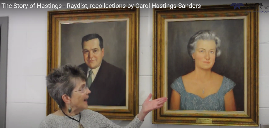
 Happy Valentine’s Day 2021
 Freeze drying, also known as lyophilization, is a process in which water molecules are removed from biological cells without damaging the cell structure. For starters, the product to be freeze-dried is chilled and the water inside is completely frozen (i.e. placed in the solid state). Next, the pressure is reduced using vacuum pumps and the water molecules sublimate – that is, water goes from the solid phase directly to the gas phase.
 View inside commercial freeze-drier