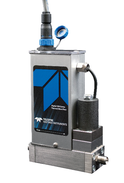
Teledyne Hastings Instruments introduced the IP-67 Enclosure Version for our high accuracy Digital 300 Series of thermal mass flow meters and flow controllers in 2018. The IP, or Ingress Protection rating, describes the instrument’s ability to operate in challenging environments. The first number, 6, indicates that the flow instrument has total protection against dust (particulate). That’s the highest-level of dust protection achievable under the IP Code. The second number, 7, refers to protection from liquids.
The Digital 300 Series with optional IP-67 enclosure can withstand water immersion up to one (1) meter for thirty (30) minutes. While it may not be obvious to everyone, it offers the liquid protection of the one meter / thirty-minute immersion as well as all lesser liquid codes (from dripping water through powerful water jets).

For more specific details on IP-67 and Ingress Protection ratings, please see our previous blog: Digital Flow Meters and Controllers now protected against dust and water - what that means for you!
What are the benefits of a mass flow meter (MFM) or mass flow controller (MFC) with IP-67 rating? It’s two-fold:
- Employee safety is every employer’s primary concern. IP-67 enclosures help to protect your employees from making accidental contact with hazardous electrical components and potential electrical shock.
- IP-67 enclosures also help protect your equipment from the ingress of solid particles and/or liquids. Most MFC enclosures contain a PCB assembly, thermal flow sensor, and a proportional control valve. By protecting your MFC from particulate contamination and/or moisture, you prolong the service-life of those components.

This protection against dust and liquids makes IP-67 MFCs ideal for demanding indoor and outdoor applications. Whether it’s a heavy-dust industrial environment or in a facility with routine sanitary washdown requirements, the Teledyne Hastings Instruments Digital 300 Series IP-67 MFCs endure.
Common applications include:
- Food and Beverage
- Heat Treating/Metals Processing
- Environmental Monitoring
- Biotech/Pharmaceutical
- Chemical/Petrochemical
- Gas Distribution

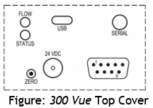
All internal components of the Digital 300 Series IP-67 MFMs and MFCs are either gasket or o-ring sealed for ingress protection. The electronics interface uses a 12-pin circular connector that facilitates Power (24vdc, Common, and Ground), Analog Input / Output (0-5vdc, 0-10vdc, 4-20mA, or 0-20mA), and Digital Communication (RS232 or RS485).
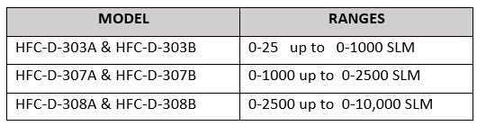
All Digital 300 Series models (sizes) are available with the IP-67 option. These sizes combine to offer complete coverage from a minimum Full Scale flow rate of 5 sccm up to a maximum Full Scale flow rate of 10,000 SLM of N2 or equivalent. Selection details for each model are illustrated in this table:
| Size | MFM Model | MFC Model | Nominal Tubing | Maximum Flow (N2 Equiv.) | IP-67 Option |
| S | HFM-D-300A | HFC-D-302A | 1/8" and 1/4" | 25 SLM | |
| M | HFM-D-301A | HFC-D-303A | 1/2" and 3/4" | 1,000 SLM | |
| L | HFM-D-305A | HFC-D-307A | 1" | 3,000 SLM | |
| XL | HFC-D-306A | HFC-D-308A | 2" | 10,000 SLM |
Most features of the Digital 300 Series MFMs and MFCs are supported by the IP-67 version. These include the totalizer, valve over-ride, soft start, fold-over protection and many more.
Visit https://www.teledyne-hi.com/en-us/what-we-do/thermal-mass-flow to learn more about Teledyne Hastings Instruments mass flow meters and mass flow controllers.
If you have questions about mass flow controllers, feel free to contact us by phone (+1-757-723-6531 or 1-800-950-2468), email Hastings_Instruments@Teledyne.com, or via Live Chat on our website www.teledyne-hi.com.

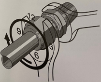
 In this blog, we will discuss various system connections, or fittings, that are available for both our mass flow and vacuum products. We will briefly explore why you might select a particular family of fittings for your system. Also, we will touch on some basic installation Dos and Don’ts.
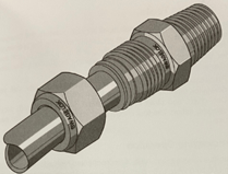
 HFC-302 with VCR fittings
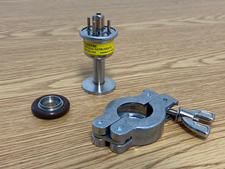 Teledyne DV-6-KF-16 (Shown with o-ring assembly and clamp)
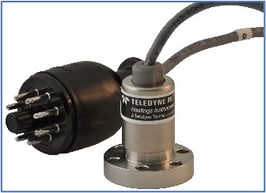 DV-6 Gauge Tube with ConFlat Flange