Have questions? Need Help?
757.723.6531 | 800.950.2468

Teledyne Hastings Instruments Blog

Understanding Piezoelectric Pressure Sensors and Piezo Pressure Vacuum Gauges

Posted by Will Harrison on Thu, Nov 20, 2014 @ 10:09 AM

Understanding Piezoelectric Pressure Sensors and Piezo Pressure Vacuum Gauges

Piezoelectric pressure sensors use a specialized material to create a small voltage when mechanical stress is applied to it. In this blog we will explain the principles behind the Piezoelectric pressure sensor, review its specific attributes and then discuss how it is used in vacuum gauge technology and industry applications.

Piezoresistive Pressure Sensors

A Piezoelectric pressure sensor functions on the principle that when mechanical stress is applied to a piezoelectric crystal, an electric potential is generated which is directly proportional to the pressure applied. A vacuum gauge that uses a piezoelectric pressure sensor typically houses the sensor in the diaphragm. This provides good linearity for vacuum transducers as the output signal correlates to the applied pressure. This signal is then used to produce an output voltage that is converted to a pressure measurement. Piezoelectric sensors are rugged and often used for measuring dynamic pressure. Because Piezoelectric sensors have a high sensitivity to dynamic changes in pressure, they are well-suited to the measurement of small changes, even in very high-pressure environments. Although they have a high sensitivity to dynamic pressure that can also be used to measure static pressures. 

Piezoelectric pressure sensors are typically used for measuring atmospheric pressure but can be paired with additional vacuum, pressure sensor technologies to create a wide-range vacuum gauge capable of measurement from vacuum to atmosphere. In some cases, a wide-range vacuum gauge can be further expanded upon by adding a 3rd technology to provide a compact solution capable of wide-range measurement from atmospheric pressure to ultra-high vacuum.

"Direct" and "Indirect" Vacuum Pressure Gauges

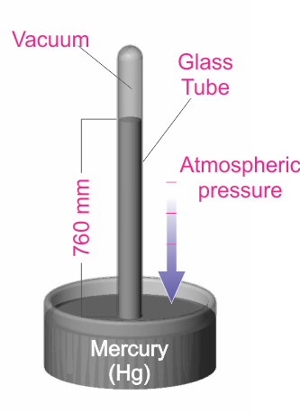
In vacuum technology, pressure measurement is accomplished using either  “Direct” or “Indirect” methods. Direct gauges are so-called because they directly measure the force imparted on a surface. Based on the formula: P = F /A (pressure (P) equals force (F) per unit area (A), the gauge directly measures the pressure. Some examples of direct gauges include: bourdon gauges, capacitance manometers and Piezoelectric gauges.
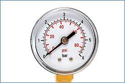
Bourdon Gauge Teledyne Hastings Instruments Framed

Bourdon Gauge

One of the primary benefits of a direct vacuum gauge is the ability to make accurate measurements regardless of gas type. For example, if the system has 20 Torr of argon, helium, methane, or air, a direct measurement gauge will read the same pressure. Because of this attribute, direct gauges are referred to as “gas composition independent”. These are helpful to see the operating pressure being used during the process. 

Indirect gauges do not “directly” measure the force associated with the gas in the chamber. Rather, these gauges measure a property associated with the gas. For example, thermocouple vacuum gauges measure the thermal conductivity of the gas, which is a function of the pressure. Another example of an indirect gauge is the pirani vacuum gauge which measures the pressure-dependent thermal conductivity of the gas in a vacuum using a heated element, such as a wire or thin-film membrane. The heated element is part of a resistance bridge. The temperature, and thus the resistance of the heated element in the vacuum, changes as the pressure changes. By measuring the electrical behavior of the bridge, the pressure in the vacuum can be determined. Consequently, thermocouple and Pirani vacuum gauges can both be called indirect gauges.

Thermocouple_Guage_Tubes_Teledyne_Hastings_Instruments_framed                 HVG 2020B Angle Finger 20.9C

 Thermocouple Gauge                     Pirani Gauge

Application: Vacuum Pressure Impregnation (VPI) Systems

Teledyne Hastings uses piezo sensors for pressure measurements in our HVG-2020A and HVG-2020B vacuum gauges. The HVG-2020A vacuum gauge uses a Piezoelectric sensor that provides accurate pressure measurement throughout the rough vacuum region. The HVG-2020B is a dual-sensor vacuum gauge that uses a Piezoelectric sensor and a Pirani sensor to measure a wide range.

Vacuum Pressure Impregnation VPI System

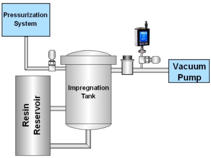
Because the HVG-2020A measures from 0.1 Torr to 1000 Torr, it is well-suited to vacuum pressure impregnation (VPI) applications. Vacuum pressure impregnation (VPI) is an important application for applying insulating materials, as well as producing void-free castings. A typical example is the encapsulation of windings in electric motors. If an insulating resin is simply “painted” on a winding, the result will be a network of uninsulated voids between the winding layers. Applying pressure may force some insulation into the voids, but the subsequent release of that pressure will cause the trapped gas to expand again, causing voids to reappear.

These voids in the insulation can lead to motor failure due to movement of the wiring during operation. Also, in high-voltage applications, these air-filled gaps can serve as sites for corona discharge formation, leading to losses in efficiency and resulting in further weakening of the dielectric.

The proper method to prepare windings, and other potted devices for impregnation, is to begin by applying vacuum.

  1. The first step is to load the assembly into a vacuum/pressure chamber and apply vacuum to remove air from the voids between the windings. A suitable pressure for this step is 5 Torr.
  2. The next step involves a two-part soak. While under vacuum, the insulating resin is introduced into the chamber from a storage vessel. The vacuum provides the additional benefit of removing any air bubbles that may be present in the resin. After a dwell period, the chamber is pressurized to 85-95 psig for another period of time. This pressurization forces the resin into the previously evacuated voids in the winding layers.
  3. After another dwell period, the pressure is relieved and the surplus resin is returned to the storage vessel. With the chamber at atmospheric pressure, it is opened and the assembly is removed. This process results in void-free application of the insulating resin on the windings.

Teledyne Hastings: HVG-2020A Vacuum Gauge

HVG 2020A_76307_finger
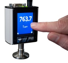
The Teledyne Hastings’ HVG-2020A vacuum gauge is a media-isolated, gas composition independent, piezoresistive instrument that provides accurate pressure measurement throughout the rough vacuum region. 

The HVG-2020A is easy to install, can be configured with an optional touchscreen display to offer a choice of data views, and provides both analog and digital output for process control integration.

  • With a wide variety of linear analog output signals to select from, the HVG-2020A is an excellent choice to replace more expensive capacitance manometers.
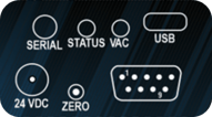
  • Digital output options include RS232 and RS485 via a connection on the top of the gauge.  A USB connection is also available on many models to make connection and operation simple.
  • Monitor and view data remotely using our free, Microsoft® Windows®-based software and log data to Microsoft® Excel® for comprehensive diagnostics that record how the vacuum behaves over time.

Analog I/O: The HVG-2020A has a 9-pin D-sub connection on top of the gauge that allows an analog output signal to be measured amongst other features.  The selected linear analog output signal is proportional to the full-scale range of the sensor (1000 Torr).

  • HVG 2020A_topAvailable outputs include: 0-1 VDC, 0-5 VDC, 0-10 VDC, 0-20 mA, and 4-20 mA.  The vacuum gauge is factory-configured with one of these outputs “active”, but can be easily changed using the touchscreen interface (if installed), or using digital communication when not configured with a touchscreen. Digital communication with the HVG-2020A will be discussed in greater depth in the next section.  
  • The 9-pin D-sub connection has Hi and Lo setpoints which are activated when the pressure is above or below the respective setpoint. Additionally, the 9-pin D-sub has a pin for input power and can accept 12-36 VDC.  For installations without 12-36 VDC, power can be supplied using a bayonet-style connector at the 24 VDC input connection.

Digitial I O for HVG 2020ADigital I/O:  As mentioned earlier, the HVG-2020A offers a variety of digital communication options in addition to the previously discussed analog choices.


  • The micro-USB connection is the simplest method to interface the vacuum gauge and allows it to be directly connected to a PC without the need for adapters or extra wiring. 
  • The 4-conductor TRRS connection can be used to “daisy-chain” multiple gauges together using RS485 or a standard RS232 communication connection. 
  • The 9-pin D-sub connection has two pins designated for TTL serial communication.
  • LabVIEW™ Drivers

All of these digital communication options (with the exception of TTL) enable PC connection and allow monitoring and viewing of data remotely using our free Microsoft® Windows®-based software.  This software has many useful features including data logging and  customization / configuration of the vacuum gauge.  Digital communication is also used to change the analog output, adjust Hi and Lo setpoint values, stream pressure readings, or change pressure units (among many other functions), when the HVG-2020A is not configured with the optional display.

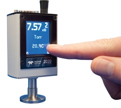
Touchscreen Display:  The most powerful feature of the HVG-2020A is the optional touchscreen display which allows monitoring of pressure measurements in a variety of combinations and graphic representations while operating. The display is powered off the vacuum gauge power supply (no additional power supply needed) and is especially useful for installations in which a remote display would be inconvenient. Five different display modes (shown left to right below) include: Pressure, Pressure and Temperature, Setpoint, Bar Graph, and Pressure over Time.  Note that the pressure measurement is always displayed in each mode. 

The touchscreen’s Menu Button allows the user to cycle through a selection of submenus to change the screen orientation (should the gauge be mounted in a position other than vertical), zero the gauge (only performed if the system pressure is known to be well below 0.1 Torr), view device information (serial number and firmware level), change the analog output, select RS232 or RS485 and a number of baud rates, and restore the vacuum gauge’s configuration to factory default settings.  The straight-forward arrangement of measurements and easy to read display, lets you “see clearly”, similar to 20/20 vision!

Applications and Industries

  • Rough Vacuum Monitoring

  • Semiconductor
  • Laser Systems
  • Chemical Research
  • Air Sampling
  • Central Vacuum Monitoring
  • Oil Reprocessing
  • Medical Research

Tags: Vacuum gauge, Sensor, pressure, vacuum pressure, vacuum instruments

Vacuum Pressure Measurement & Unit Guide

Posted by Doug Baker on Mon, Sep 22, 2014 @ 04:23 PM

Note: The content of this blog was updated February 4, 2023 to provide more information for the reader.

The applications engineers here at Teledyne Hastings discussed topics for our blog. We all agreed that one of the more frequent questions fielded, involves the units used to measure vacuum levels. We find that the technicians who use their vacuum system daily often seem to develop a sixth sense about the “health” of their systems. They know something isn’t quite right when the base vacuum pressure (or rate of pressure change) is not what they expect. So, when vacuum pressure measurements are inconsistent from batch-to-batch, that is the time when the user stops to ask the meaning behind the data that their vacuum measurement instrumentation is providing.

Measuring Vacuum Pressures

A vacuum exists when there is negative pressure, or when there is system pressure that is less than atmospheric pressure. Manufacturing processes generate different levels of vacuum when operating at peak efficiency for a given vacuum application that are measured using a vacuum gauge. Absolute vacuum is the absence of all matter. Atmospheric pressure, also known as barometric pressure, is the pressure due to earth’s atmosphere. Atmospheric pressure is 760 Torr or 14.696 psia at sea level and changes with altitude. The vacuum pressure scale is book-ended by absolute vacuum pressure in the “ultra-high” vacuum range and atmospheric pressure at the “rough” vacuum range. It should be noted that absolute vacuum, or perfect vacuum, is never truly attained.

Most users know that vacuum is commonly measured using units of pressure. There are a few different systems of pressure measurement, and this blog will discuss those most used. In Armand Berman’s book, Total Pressure Measurements in Vacuum Technology, pressure unit systems are divided into two categories: “Coherent Systems” and “Other Systems”.

Common Units of Vacuum

“Coherent Systems” of units are based on the definition of pressure (P) as the force (F) exerted on a chamber wall per unit area (A). P = F/A. The International System of Units, or SI units, is commonly used for pressure measurement. http://physics.nist.gov/cuu/Units/units.html The SI unit for pressure is the Pascal (Pa), and it is interesting to note that NIST (National Institute of Standards and Technology) published papers are always required to use SI units. Again, the SI unit for pressure (force per unit area) is the Pascal. 1 Pa = 1 N /m2.

As a unit of pressure, the Pascal is not always convenient to use because vacuum systems often operate in pressure ranges where collected data results in large numbers. For example, near atmospheric pressure, we would measure approximately 100,000 Pa. So, a more convenient unit, the bar, was developed. (1 bar = 100,000 Pa)

Moving lower in pressure, it is very helpful to then use the mbar (1 mbar = 0.001 bar), which has become the predominate unit of measure in Europe, as the basis for describing pressure levels. As a specific example, look at the base pressure specification of a turbo pump, which will typically be given in terms of mbar (e.g., Base Pressure < 1 x 10⁻¹⁰ mbar).

“Other Systems” of units include the Torricelli system, which is based on an experiment (shown in the diagram below) conducted by the Italian scientist, Evangelista Torricelli. In this experiment, the pressure exerted on the mercury can be shown to be P = hdg, where h is the height of the mercury column, d is the density, and g is the acceleration due to gravity.

Simple Barometer

By measuring the mercury column height, the pressure can be determined. The Torr unit (named after Torricelli) has been defined as 1 millimeter of mercury (1 Torr = 1 mmHg). This unit, as well as the use of the mTorr unit (1 mTorr = 0.001 Torr), is commonly used in the United States. Historically, pressure was sometimes described in terms of “microns”, which simply meant a mercury column height of one micron (1x10⁻⁶ m). Note that the micron and the mTorr are the same.

Lastly, it should be noted that occasional confusion arises between the use of different, but seemingly similar, units of pressure. As explained above, the mbar and the mTorr are not the same. One mbar has the same order of magnitude as one Torr (1 mbar = 0.75 Torr).


Unit Conversions

The table below gives some conversion values between various commonly used units of pressure and vacuum. A useful website for conversions:

http://www.onlineconversion.com/pressure.htm


Pa

mbar

Torr

mTorr (micron)

Atm

1 Pa =

1

0.01

0.0075

7.50

~ 10-5

1 mbar =

100

1

-.75

750.06

~ 10-3

1 Torr =

133.3

1.333

1

1000.0

~ 10-3

1 mTorr (micron) =

0.1333

0.00133

0.001

1

~ 10-6

1 Atm =

101,325

1013.25

760

760,000

1


Absolute Pressure and Gauge Pressure

In conclusion, keep in mind that vacuum measurements can be referenced to ambient pressure, gauge pressure measurement or absolute pressure measurement (perfect vacuum). An absolute pressure measurement is referenced with respect to absolute vacuum. Absolute pressure will often be designated by the letter “a” after the unit of measure; “psia.” ​As an example, an absolute pressure reading of 30 psia (pounds per square inch absolute) is a pressure that is 30 psi above vacuum. It is important to understand that there is no negative absolute pressure. There are some

Gauge pressure measurements are measured relative to the ambient atmospheric pressure. Relative, or gauge pressure, will often be designated by the letter “g” after the unit of measure; “psig.” As an example, 30 psig is a gauge pressure that is 30 psi above ambient atmosphere (typically 14.7 psia at sea level). In this example the gauge pressure, 30 psig, is equal to an absolute pressure of 44.7 psia.


What is a vacuum system?

A vacuum system can consist of multiple a vacuum pumps and vacuum gauges attached to a tank that is designed to measure below atmospheric pressure. The vacuum pumps reduce the air pressure inside of the tank to the pressure range that the vacuum pump is rated for. Different vacuum pumps bring the vacuum pressure to different levels depending on the strength of the vacuum pump.

Attached to the tank is usually at least one vacuum pressure gauge. An application may require another type of vacuum gauge to measure a different pressure point. An example of this would be using a piezo pressure gauge and a Pirani pressure gauge to have a larger range of the vacuum pressure measured. A piezo vacuum gauge would be used to measure the rough vacuum range around atmosphere and the Pirani could be used to measure below 1 Torr in the mTorr range. There are vacuum gauges that use technologies from different vacuum gauges to create a combination vacuum gauge to measure vacuum pressure across a wider pressure range. Teledyne Hastings combines both the Pirani and piezo technologies to make the HVG-2020B vacuum pressure gauge.


Vacuum Gauges Poster

Mass Flow - Vacuum Gauge Posters

Vacuum Gauges
Free Poster
Unit Conversions and More

Please send me the poster(s)


Original Content posted Sept 22, 2014

FAQ Corner - Units for Vacuum Measurement
an overview of units used to measure pressure

Earlier this year, the applications engineers here at Teledyne Hastings discussed topics for our blog. We all agreed that one of the more frequent questions that we discuss with folks involve the units used to measure vacuum levels. We find the technicians who use their vacuum systems daily often seem to develop a sixth sense about the “health” of their systems. They know something isn’t quite right when the base pressure (or rate of pressure change) is not what they expect. So, when pressure measurements are not consistent from batch to batch, that is the time when the user stops to ask the meaning behind the data that their vacuum measurement instrumentation is providing.

Now, most users know that vacuum is commonly measured using units of pressure. There are a few different sets of pressure units, and this blog will discuss the more commonly used ones. In Armand Berman’s book, Total Pressure Measurements in Vacuum Technology, pressure unit systems are divided into two categories: “Coherent Systems” and “Other Systems”.

Coherent Systems of Units are based on the definition of pressure (P) as the force (F) exerted on a chamber wall per unit area (A). P = F/A.  The International System of Units, or SI units, is commonly used for pressure measurement. http://physics.nist.gov/cuu/Units/units.html  The SI unit for pressure is the Pascal (Pa). It interesting to note that at NIST (National Institute of Standards and Technology), published papers are always required to use the SI set of units. Again, the SI unit for pressure (force per unit area) is the Pascal. 1 Pa = 1 N /m2.

Now, the Pascal as a unit of pressure is not always the most convenient because vacuum systems are often operating in a range of pressures where we would need to collect data using large numbers. For example, near atmospheric pressure, we would measure approximately 100,000 Pa. So, a more convenient unit, the bar, has been derived. (1 bar = 100,000 Pa)

Moving lower in pressure, it is very helpful to then use the mbar (1 mbar = 0.001 bar). So many vacuum users, especially in Europe, use the mbar as the basis for describing pressure levels. As a specific example, look at the base pressure specification of a turbo pump, it will be given in terms of mbar (e.g. Base Pressure < 1 x 10⁻¹⁰ mbar).

Another system of pressure units is based on the Torricelli experiment (shown in the diagram). In this experiment, the pressure exerted on the mercury can be shown to be P = hdg, where h is the height of the mercury column, d is the density, and g is the acceleration due to gravity.

Simple Barometer

By measuring the mercury column height, the user can determine the pressure. The Torr unit (named for the Italian scientist Torricelli) has been defined to be 1 millimeter of mercury (1 Torr = 1 mmHg). This unit is very common, especially in the United States. It is also common to use the mTorr (1 mTorr = 0.001 Torr). Many years ago, pressure was sometimes described in terms of “microns”, which simply meant a mercury column height of one micron (1x10⁻⁶ m). Note that the micron and the mTorr are the same.

One last word about the units used to measure vacuum: on occasion, there is confusion between pressure units. As we have seen above, the mbar and the mTorr are not the same. One mbar has the same order of magnitude as one Torr  (1 mbar ≈ 0.75 Torr).  The table below gives some approximate conversion values. A useful website for conversions:

 http://www.onlineconversion.com/pressure.htm


Pa

mbar

Torr

mTorr (micron)

Atm

1 Pa =

1

0.01

0.0075

7.50

~ 10-5

1 mbar =

100

1

0.75

750.06

~ 10-3

1 Torr =

133.3

1.333

1

1000.0

~ 10-3

1 mTorr (micron) =

0.1333

0.00133

0.001

1

~ 10-6

1 Atm =

101,325

1013.25

760

760,000

1

Douglas Baker is the Director of Sales & Business Development of Teledyne Hastings. Antonio Araiza prepared the Torricelli experiment drawing. Antonio is the head of Technical Documentation at Teledyne Hastings (and is among the best soccer referees in the Commonwealth of Virginia).

Tags: Teledyne Hastings Instruments, pressure, mTorr, mBar, micron, pascal, torr, vacuum pressure, units of measurement, vacuum gauges, vacuum meters, vacuum controllers

FAQ Corner – Specifying range, pressures on Mass Flow Instruments

Posted by Wayne Lewey on Wed, May 29, 2013 @ 10:01 AM

We often see the label “One Size Fits All”.  This may be fine for some consumer goods.  However, it can be quite problematic when applied to items like shirts, gloves, or even golf clubs.  “One Size Fits All” also does not work for Mass Flow Controllers (MFC).  Not all applications are alike.  Forcing a “One Size Fits All” MFC into an unsuitable application can squander accuracy and induce valve failure.

Why do you need to specify the gas flow range on a MFC?  The Full Scale (FS) Range and Gas on a MFC directly correlates to the transmitted output (analog or digital) of the device.  In an analog device, the maximum output value (such as 5 vdc or 20 mA) will be equivalent to the FS value.  The accuracy of most MFCs is a function of this FS Range.  For analog devices, it is commonly ±1% of FS.  For digital devices, it is commonly published to be ±(0.5% of Reading + 0.2% FS).  Selecting the FS Range close to an application’s maximum flow rate optimizes accuracy for that specific application.  This is a good practice.  In addition, the gas must be specified.  Most MFCs use thermal based sensors.  These sensors actually measure the molecular flow rate rather than the mass flow rate.  Various gas molecules transfer heat differently, and thus the gas must be known.

Why do you need to specify Upstream Pressure and Downstream Pressure on a MFC?  Again, not all applications are the same.  A “One Size Fits All” MFC is typically not set up for applications at high pressure, low pressure, high differential pressure, or low differential pressure.  The definition of high and low will also fluctuate from one user to another.  Teledyne Hastings Instruments selects and tests MFC valve components (orifice, spring, etc.) that optimize valve stability for the exact application pressure conditions.When using a Teledyne Hastings Instruments MFC, you will always find the FS Range / Gas and the Upstream / Downstream Pressures listed on the serial number label.

Sample Calibration Sticker for MFC


Wayne Lewey was first exposed to mass flow controllers while an undergraduate at North Carolina State University (Chemical Engineering).  Today, Wayne is the International Sales Manager at Teledyne Hastings Instruments and can be reached at wlewey@teledyne.com.

Tags: Teledyne Hastings Instruments, Flow Controller, Gas Flow Range, pressure, range, differential pressure, mass flow controller, mass flow meter