Have questions? Need Help?
757.723.6531 | 800.950.2468

Teledyne Hastings Instruments Blog

Will Harrison

Recent Posts

What is a Thermal Mass Flow Meter & What is its Working Principle? - Part 1 of 2

Posted by Will Harrison on Fri, Mar 20, 2015 @ 10:59 AM

ThermalMassFlowSensorCutawayThis is part 1 of a 2-part blog on the Thermal Mass Flow Meter.  In Part 1 we will explain the desired characteristics of a mass flow meter (and its sensor). Part 2 will discuss the operation of the Teledyne Hastings 300 Series flow meters (Patent #6,125,695) and how the 300 Series thermal mass flow sensor meets each of the desired characteristics described below.

What is a thermal mass flow meter:

  • Electronic Circuit Card

  • Flow Sensor

  • Bypass Shunt

  • Base

A cutaway is shown in the image on the right.

A flow meter measures the amount of fluid that passes through the meter. At Teledyne Hastings we design our thermal mass flow meters for dry and clean gases. This is useful for wide array applications that include measuring natural gas or air and biogas measurement.

In a typical mass flow meter, gas enters the meter via an upstream port connected to the process to be measured (by Swagelok®, VCR®    or other fitting).  A majority of the gas passes through the meter’s bypass shunt; however, a certain fraction flows through the meter’s thermal flow sensor.

The meter’s thermal mass flow sensor measures the gas molecular flow that passes through its capillary tube by quantitating thermal energy transfer. The mass flow rate is a function of the gas flow and the specific heat of the gas. The thermal mass flow sensor then provides accurate measurements which can be referenced back to standardized volumetric flow units.  Reference conditions (standard temperature and pressure) are based upon the amount of gas flow, which is determined by the number of gas molecules, using the ideal gas law. The meter’s shunt is selected such that the amount of gas moving through the flow sensor is approximately the same at full-scale flow. After passing through the thermal mass flow sensor, the gas then exits the flow meter via a downstream port.

Thermal Mass Flow Meter Characteristics

FlowSensorOutput

Ideally, a thermal mass flow sensor will exhibit the following characteristics:

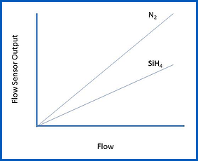
  • Linearity: Linearity means that the sensor’s electronic output is directly proportional to the rate of gas flow that is moving through the sensor (within its range). Linearity of the flow sensor leads to the second attribute: Accuracy.
  • Accuracy: Accuracy is dependent on the sensor’s Linearity. An accurate flow sensor provides the benefits of better gas thermal flow measurement, flow control and a thorough understanding of the system’s parameters.
  • Fast Response:  Ideally, the flow sensor would respond instantaneously to a change in the mass flow rate. Aside from the obvious benefit of instant real-time oversight of the process flow, fast response becomes critical when the flow meter is coupled with a proportional control valve to create a thermal mass flow controller.
  • Low Differential Drop: For a flow sensor to be ideal for leak testing, it should have a low differential pressure drop across the meter. 

Typically, a mass flow meter is calibrated using nitrogen gas (or in the case of very large flows, it may be calibrated in air). The output of the flow meter can then be scaled for use with other process gases. This means the flow meter technician can calibrate a flow meter for use with a corrosive process gas, such as silane (SiH4), without having to use that specific type of gas. A linear flow sensor will retain its linear behavior as the gas is switched from the calibration gas (N2) to the process gas.

How does a thermal mass flowmeter work?

When gas is flowing through the bypass shunt, a small pressure drop is developed which will direct a fraction of the flow through the arced / semi-circular capillary tubing in the flow sensor. On the outside of the capillary tube, there are two resistive wire coils that act as temperature sensors which are tightly wound and in excellent thermal contact with the tube. These two identical windings are referred to as:

  • Upstream Heater Coil (1)
  • Downstream Heater Coil (2)

Associated with each of the two heated coils is an ambient coil. The ambient coil is in excellent thermal contact with the aluminum ambient block.  Aluminum has a very high thermal conductivity which ensures that both ends of the sensor tube and the two ambient coils (3 and 4) will be at the same temperature. 

Upstream - Downstream Heater Coil Image
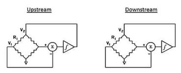
Two identical Wheatstone resistance bridges are formed from the two pair of coils (see image on right).

The circuit shown in the image on the right is designed to ensure that the heated sensor (upstream and downstream) are maintained at a constant temperature differential (ΔT) above the corresponding ambient coils.

Next, we calculate the power (W) required to maintain ΔT by:

Power requires to maintain T

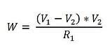
This power will be calculated for both the upstream bridge and the downstream bridge. It can be shown that: 

Upstream - Downstream Bridge calculation

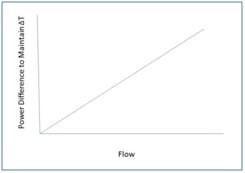
So, by maintaining both heaters at the same temperature difference (ΔT) above ambient, the mass flow rate is directly proportioned to the difference in power (W) between the two bridges. For example, when no flow is passing through the capillary sensor tube, the power needed to maintain that temperature difference (ΔT) will be the same (i.e. ṁ = 0)

As gas flow increases in the tube, heat is transferred from the upstream heater to the gas stream.  This will force the upstream circuit to use more power to maintain ΔT. In turn, the gas will transfer heat to the downstream heater which will cause the downstream circuit to use less power to maintain ΔT.

Now, here is the best part: the mass flow rate is directly proportional to the power difference. In other words, Linearity!

Linearity

Application

Measuring gas flows has become increasingly critical to many processes and the mass flow meter achieves those results with a high level of accuracy.  Accurate readings must reference standard temperature and pressure (STP) conditions, without having to correct for temperature and pressure using volumetric flow meters. Typically this requires a temperature compensation for the fluid temperature. Using this method is also not a direct mass measurement because the only direct measurement taken is of the fluid temperature. This can be used for heavy gases such as natural gas or gases as light as hydrogen.

Thermal mass flow meters exhibiting low pressure differentials are ideal for measuring flow in leak testing applications and must provide fast response and accurate gas flow readings.

Teledyne Hastings designed its first fast-response flow meter for leak testing applications in the automotive industry. The low-pressure differential and response speed proved to be highly successful. Today, Teledyne Hastings' Thermal Mass Flow Sensors are used globally in a variety of diverse industries and applications.  For more information on Best Practices for Flow Controllers and Thermal Mass Flow Meters download our whitepaper.

Download Whitepaper

Be sure to visit our website for additional information on Teledyne Hastings Mass Flow Controllers and Mass Flow Meters

In our next blog, we will discuss the thermal mass flow sensor at the heart of Teledyne 300 Series of mass flow meters. We will also look at how the 300 Series thermal mass flow sensor meets each of the desired characteristics described above.

Tags: Thermal Flow

Understanding Piezoelectric Pressure Sensors and Piezo Pressure Vacuum Gauges

Posted by Will Harrison on Thu, Nov 20, 2014 @ 10:09 AM

Understanding Piezoelectric Pressure Sensors and Piezo Pressure Vacuum Gauges

Piezoelectric pressure sensors use a specialized material to create a small voltage when mechanical stress is applied to it. In this blog we will explain the principles behind the Piezoelectric pressure sensor, review its specific attributes and then discuss how it is used in vacuum gauge technology and industry applications.

Piezoresistive Pressure Sensors

A Piezoelectric pressure sensor functions on the principle that when mechanical stress is applied to a piezoelectric crystal, an electric potential is generated which is directly proportional to the pressure applied. A vacuum gauge that uses a piezoelectric pressure sensor typically houses the sensor in the diaphragm. This provides good linearity for vacuum transducers as the output signal correlates to the applied pressure. This signal is then used to produce an output voltage that is converted to a pressure measurement. Piezoelectric sensors are rugged and often used for measuring dynamic pressure. Because Piezoelectric sensors have a high sensitivity to dynamic changes in pressure, they are well-suited to the measurement of small changes, even in very high-pressure environments. Although they have a high sensitivity to dynamic pressure that can also be used to measure static pressures. 

Piezoelectric pressure sensors are typically used for measuring atmospheric pressure but can be paired with additional vacuum, pressure sensor technologies to create a wide-range vacuum gauge capable of measurement from vacuum to atmosphere. In some cases, a wide-range vacuum gauge can be further expanded upon by adding a 3rd technology to provide a compact solution capable of wide-range measurement from atmospheric pressure to ultra-high vacuum.

"Direct" and "Indirect" Vacuum Pressure Gauges

In vacuum technology, pressure measurement is accomplished using either  “Direct” or “Indirect” methods. Direct gauges are so-called because they directly measure the force imparted on a surface. Based on the formula: P = F /A (pressure (P) equals force (F) per unit area (A), the gauge directly measures the pressure. Some examples of direct gauges include: bourdon gauges, capacitance manometers and Piezoelectric gauges.

Bourdon Gauge Teledyne Hastings Instruments Framed

Bourdon Gauge

One of the primary benefits of a direct vacuum gauge is the ability to make accurate measurements regardless of gas type. For example, if the system has 20 Torr of argon, helium, methane, or air, a direct measurement gauge will read the same pressure. Because of this attribute, direct gauges are referred to as “gas composition independent”. These are helpful to see the operating pressure being used during the process. 

Indirect gauges do not “directly” measure the force associated with the gas in the chamber. Rather, these gauges measure a property associated with the gas. For example, thermocouple vacuum gauges measure the thermal conductivity of the gas, which is a function of the pressure. Another example of an indirect gauge is the pirani vacuum gauge which measures the pressure-dependent thermal conductivity of the gas in a vacuum using a heated element, such as a wire or thin-film membrane. The heated element is part of a resistance bridge. The temperature, and thus the resistance of the heated element in the vacuum, changes as the pressure changes. By measuring the electrical behavior of the bridge, the pressure in the vacuum can be determined. Consequently, thermocouple and Pirani vacuum gauges can both be called indirect gauges.

Thermocouple_Guage_Tubes_Teledyne_Hastings_Instruments_framed                 HVG 2020B Angle Finger 20.9C

 Thermocouple Gauge                     Pirani Gauge

Application: Vacuum Pressure Impregnation (VPI) Systems

Teledyne Hastings uses piezo sensors for pressure measurements in our HVG-2020A and HVG-2020B vacuum gauges. The HVG-2020A vacuum gauge uses a Piezoelectric sensor that provides accurate pressure measurement throughout the rough vacuum region. The HVG-2020B is a dual-sensor vacuum gauge that uses a Piezoelectric sensor and a Pirani sensor to measure a wide range.

Vacuum Pressure Impregnation VPI System

Because the HVG-2020A measures from 0.1 Torr to 1000 Torr, it is well-suited to vacuum pressure impregnation (VPI) applications. Vacuum pressure impregnation (VPI) is an important application for applying insulating materials, as well as producing void-free castings. A typical example is the encapsulation of windings in electric motors. If an insulating resin is simply “painted” on a winding, the result will be a network of uninsulated voids between the winding layers. Applying pressure may force some insulation into the voids, but the subsequent release of that pressure will cause the trapped gas to expand again, causing voids to reappear.

These voids in the insulation can lead to motor failure due to movement of the wiring during operation. Also, in high-voltage applications, these air-filled gaps can serve as sites for corona discharge formation, leading to losses in efficiency and resulting in further weakening of the dielectric.

The proper method to prepare windings, and other potted devices for impregnation, is to begin by applying vacuum.

  1. The first step is to load the assembly into a vacuum/pressure chamber and apply vacuum to remove air from the voids between the windings. A suitable pressure for this step is 5 Torr.
  2. The next step involves a two-part soak. While under vacuum, the insulating resin is introduced into the chamber from a storage vessel. The vacuum provides the additional benefit of removing any air bubbles that may be present in the resin. After a dwell period, the chamber is pressurized to 85-95 psig for another period of time. This pressurization forces the resin into the previously evacuated voids in the winding layers.
  3. After another dwell period, the pressure is relieved and the surplus resin is returned to the storage vessel. With the chamber at atmospheric pressure, it is opened and the assembly is removed. This process results in void-free application of the insulating resin on the windings.

Teledyne Hastings: HVG-2020A Vacuum Gauge

HVG 2020A_76307_finger
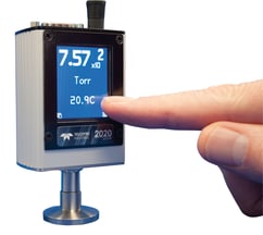
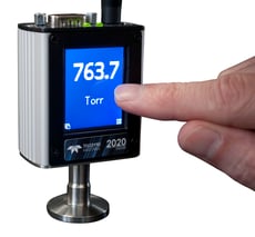
The Teledyne Hastings’ HVG-2020A vacuum gauge is a media-isolated, gas composition independent, piezoresistive instrument that provides accurate pressure measurement throughout the rough vacuum region. 
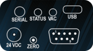
The HVG-2020A is easy to install, can be configured with an optional touchscreen display to offer a choice of data views, and provides both analog and digital output for process control integration.

  • With a wide variety of linear analog output signals to select from, the HVG-2020A is an excellent choice to replace more expensive capacitance manometers.
  • Digital output options include RS232 and RS485 via a connection on the top of the gauge.  A USB connection is also available on many models to make connection and operation simple.
  • Monitor and view data remotely using our free, Microsoft® Windows®-based software and log data to Microsoft® Excel® for comprehensive diagnostics that record how the vacuum behaves over time.

Analog I/O: The HVG-2020A has a 9-pin D-sub connection on top of the gauge that allows an analog output signal to be measured amongst other features.  The selected linear analog output signal is proportional to the full-scale range of the sensor (1000 Torr).

  • HVG 2020A_topAvailable outputs include: 0-1 VDC, 0-5 VDC, 0-10 VDC, 0-20 mA, and 4-20 mA.  The vacuum gauge is factory-configured with one of these outputs “active”, but can be easily changed using the touchscreen interface (if installed), or using digital communication when not configured with a touchscreen. Digital communication with the HVG-2020A will be discussed in greater depth in the next section.  
  • The 9-pin D-sub connection has Hi and Lo setpoints which are activated when the pressure is above or below the respective setpoint. Additionally, the 9-pin D-sub has a pin for input power and can accept 12-36 VDC.  For installations without 12-36 VDC, power can be supplied using a bayonet-style connector at the 24 VDC input connection.

Digitial I O for HVG 2020ADigital I/O:  As mentioned earlier, the HVG-2020A offers a variety of digital communication options in addition to the previously discussed analog choices.


  • The micro-USB connection is the simplest method to interface the vacuum gauge and allows it to be directly connected to a PC without the need for adapters or extra wiring. 
  • The 4-conductor TRRS connection can be used to “daisy-chain” multiple gauges together using RS485 or a standard RS232 communication connection. 
  • The 9-pin D-sub connection has two pins designated for TTL serial communication.
  • LabVIEW™ Drivers

All of these digital communication options (with the exception of TTL) enable PC connection and allow monitoring and viewing of data remotely using our free Microsoft® Windows®-based software.  This software has many useful features including data logging and  customization / configuration of the vacuum gauge.  Digital communication is also used to change the analog output, adjust Hi and Lo setpoint values, stream pressure readings, or change pressure units (among many other functions), when the HVG-2020A is not configured with the optional display.

Touchscreen Display:  The most powerful feature of the HVG-2020A is the optional touchscreen display which allows monitoring of pressure measurements in a variety of combinations and graphic representations while operating. The display is powered off the vacuum gauge power supply (no additional power supply needed) and is especially useful for installations in which a remote display would be inconvenient. Five different display modes (shown left to right below) include: Pressure, Pressure and Temperature, Setpoint, Bar Graph, and Pressure over Time.  Note that the pressure measurement is always displayed in each mode. 

The touchscreen’s Menu Button allows the user to cycle through a selection of submenus to change the screen orientation (should the gauge be mounted in a position other than vertical), zero the gauge (only performed if the system pressure is known to be well below 0.1 Torr), view device information (serial number and firmware level), change the analog output, select RS232 or RS485 and a number of baud rates, and restore the vacuum gauge’s configuration to factory default settings.  The straight-forward arrangement of measurements and easy to read display, lets you “see clearly”, similar to 20/20 vision!

Applications and Industries

  • Rough Vacuum Monitoring

  • Semiconductor
  • Laser Systems
  • Chemical Research
  • Air Sampling
  • Central Vacuum Monitoring
  • Oil Reprocessing
  • Medical Research

Tags: Vacuum gauge, Sensor, pressure, vacuum pressure, vacuum instruments