
As I go through the day looking at various mass flow applications, I often notice that it is very easy for users to overlook one of the crucial items required for calculating mass flow. Looking at an application with its established requirements, we often jump right to determining “what flow rate is required?” However, it is important to remember that mass flow applications using volumetric units must reference a standard temperature and pressure. But why is this the case?
When examining liquid flow instruments, we know that liquids are incompressible and thus the amount of a substance present is determined by the volume being used. This leads to a simple calculation using density with the already determined volume to find the mass present in the volume or the volumetric flow.
 Gases, however, ARE compressible and so the volume is only one factor in determining the amount of material being measured. If we look at the ideal gas law that you may remember from a chemistry class school (PV = nRT), we understand that temperature (T) and pressure (P) must also be considered in the equation. Otherwise it is impossible for us to know “how much” of the substance (n) there is in the space (V) or flowing through the system.
But given all of this information do we actually end up with the mass flow? The actual quantification of this “how much” calculation is expressed in moles (n), which is an extremely large number of molecules of a gas stated as Avogadro’s number, equal to 6.02x10²³ (Don’t be scared by this value, though. A mole is a number, just like one dozen is 12, so one mole is 6.02x10²³ molecules). Since the number of molecules of a gas and the mass are directly related for each gas type (i.e. molar mass), we are able to calculate the mass of the volume or volumetric flow based on the number of moles present. This is based on the assumption that the measured gas is pure and not contaminated with any other gases.
We’ll look at an example of the difference of STP conditions in a mass flow meter. Teledyne Hastings Instruments assumes STP of 0°C and 760 Torr, but would prefer the customer to specify their STP conditions for the application. We will use the frequently referenced STP of 20°C and 760 Torr for the second part of this example. Suppose that we are looking to measure 1 SLM (Standard Liter per Minute) of Nitrogen gas. As I’ve discussed earlier, the 1 SLM must be referenced to an STP value, so we will use our assumed conditions of 0°C and 760 Torr. If we were to change to the second set of conditions, the number of moles present in the flow (Molar Flow Rate) would change, and our mass flow rate would thus change (based on the direct relationship between mass and moles). Our initial mass flow rate of 1 SLM of Nitrogen at 0°C and 760 Torr would now be 1.074 SLM of Nitrogen at 20°C and 760 Torr.
 An important item to note is that the STP conditions are not actually present during the calibration of mass flow meters and mass flow controllers. Gas conditions are not brought to 0°C and 760 Torr prior to running calibration of equipment. The substance may not even be in gas phase at 0°C. The STP conditions are simply stated to define the standard volumetric flow rates of a substance IF it were an ideal gas at standard conditions.
This is also the reasoning for the addition of the “S” or “Standard” at the start of the stated volumetric flow rate (e.g. Standard Liters per Minute (SLM) or Standard Cubic Centimeters per Minute (SCCM)). We are stating the volumetric flow that would be present using standard conditions. So, using the information that we learned earlier, by stating the units in Standard Volumetric Flow Rate we are actually stating the Molar Flow Rate. This information changes based on the standards we are referencing and emphasizes the importance of stating the required STP conditions.
We welcome your comments and your questions about mass flow. Please complete the form below:

Brandon Hafer is an Application Engineer with Teledyne Hastings Instruments. He completed his undergraduate degree studying meteorology at the Pennsylvania State University before serving as an officer in the United States Navy. He received his master’s degree in Systems Engineering from George Washington University and has been with Teledyne Hastings Instruments for two years. If you would like to contact him, he can be reached at brandon.hafer@teledyne.com.
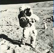 The history of the Hastings Instruments Company stretches all the way back to 1944. Next year, Hastings will celebrate its 70th birthday. But while we are in a corporate history mood, it might be fun to recall everybody’s favorite Hastings’ story: In 1967, Hastings vacuum sensors were designed to travel to the moon and back. One of the objectives of the Apollo missions was to bring lunar samples back to earth. Special boxes, fitted with Hastings vacuum thermocouples were designed and built by Oak Ridge National Labs. Each box was required to be vacuum sealed; the Hastings thermocouple ensured that the seal was good before launch, and after splash down. The box and sensor worked perfectly. Today, the thermopiles from the Apollo 14 mission are on display on a wall between one of the company’s conference rooms and a hallway. A magnifying lens and lamp installed in the display allows visitors to see the vacuum sensor.
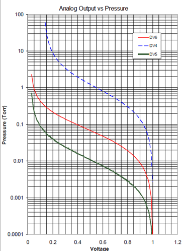 In order to better understand the accuracy of a thermocouple vacuum gauge, it is helpful to review the response curve of these vacuum gauges. In the accompanying figure, we show the output of three of Teledyne Hastings most popular vacuum gauges. Note that each vacuum gauge tube family (DV-4, DV-5, and DV-6) has a range of pressures where the sensitivity, defined as the change in output as a function of pressure is very good. In this pressure region, the output is very repeatable and gives the best accuracy. Note that at the far ends of the curves, the sensitivity flattens out which in turn causes more uncertainty in the pressure measurement. So in general, the best accuracy of the thermocouple gauge is found in the middle of the curve. This fact can help the user select the best vacuum gauge tube family for a given application. Note that the measurement accuracy reflects the gauge as a whole system (meter, cable, and thermocouple gauge tube) and not the individual components. (So, it does not make sense to ask, what the accuracy of a thermocouple gauge tube is.) Users can look up their pressures by reading their output voltages. The voltage shown here is an amplified signal derived from the thermocouple output.