
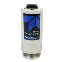
We at Teledyne Hastings Instruments are pleased to introduce the newest member of our vacuum measurement portfolio, the HVGPR. The HVGPR vacuum gauge measures pressures from Atmosphere to 0.1 mTorr (1.3 x 10⁻⁴ mbar / 1.3 x 10⁻² Pascal). It uses the same precision pirani sensor found in our proven HVG-2020B wide range gauge. The HVGPR is packaged in a compact and cost-effective design that makes it ideal for OEMs, system integration, and process automation.
Accuracy
The HVGPR measures from Atmosphere through Medium Vacuum (0.1 mTorr / 1.3 x 10⁻⁴ mbar / 1.3 x 10⁻² Pascal). It has great accuracy from 1 mTorr to 100 mTorr while still providing visibility at atmosphere. Most applications use N2 or Air, but the HVGPR has preset gas correction factors to also cover He, Ar, H2, CF4, and SF6.
| Range | Accuracy |
| 100 Torr to 1,000 Torr | ± 50% of Rdg |
| 1 mTorr to 100 Torr | ± 15% of Rdg |
| 0.1 mTorr to 1 mTorr | ± (50% of Rdg + 0.1 mTorr) |
System Connections
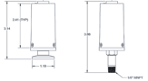
The HVGPR is available with two small system connections for system integration: KF-16 flange or 1/8” MNPT. Unlike some pirani vacuum gauges, the HVGPR can be mounted and operate in any orientation: port facing down, port facing up, port facing sideways, port tilted at an angle, etc.
Analog Output and Digital Communication
Both models offer two choices of common logarithmic analog output signals for simple integration into OEMs and process automation: 1 V/decade (2-9 VDC) or 1.286 V/decade (1.16-10.1620). The user can easily change from one output to the other. In addition, RS485 digital communication is standard on all units. Power, analog output, and digital communication are provided through a single RJ45 connector.
| Output | @ 0.001 Torr | @ 1,000 Torr | P (Torr) from V (volts) | Volts from P (Torr) |
| 1.00 V/decade | 2.0000 V | 9.000 V | P=10(v-6) | V=log10P+6 |
| 1.286 V/decade | 1.1600 V | 10.1620 V | P=100.778(V-6.304) | V=1.286 log10P+6.304 |
Other Features
A status LED on the top panel flashes to allow you to approximate your pressure with a quick glance.
The gauge offers three simple ways to Zero or Span the unit:

-
Recessed Push Button,
-
Remote Pins 7 & 2
-
RS485
Applications
The HVGPR is ideal for a wide variety of vacuum applications, but it’s compact size and flexibility make it excellent for OEMs, system integration, and process automation.
Common Analytical Instrumentation OEM applications include but are not limited to: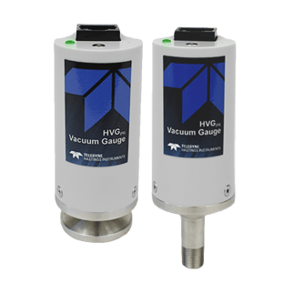
- Vacuum Centrifuge
- Surface Porosity
- Optical Emission Spectrometers
- High Pressure Metrology
Other common applications include:
- Semiconductor
- Foreline Monitoring
- Glass Coating
- Thin Film Deposition
- Freeze Drying
- Vacuum Furnace / Heat Treat
- HVAC / Refrigeration / Ice Machinery
- Oil Reprocessing
Visit https://www.teledyne-hi.com/en-us/what-we-do/hvg-pr to learn more about the HVGPR vacuum gauge.
If you have questions about vacuum gauges or vacuum controllers, feel free to contact us by phone (+1-757-723-6531 or 1-800-950-2468), email Hastings_Instruments@Teledyne.com, or via Live Chat on our website www.teledyne-hi.com.


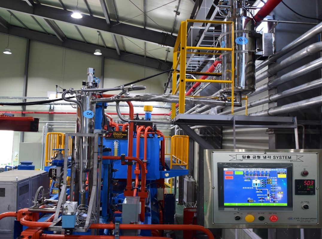
 InfoRAD Corp. was a part of Applied Engineering which became a distributor for Teledyne Hastings Instruments in 1983. Applied Engineering decided to spin-off InfoRAD in 2003, and InfoRAD immediately began the transition from a pure sales office to a complete sales, calibration, repair, and custom system design facility. They support customers across South Korea from their headquarters in the M-City Tower in Goyang. The office sits on Seoul’s northwest edge which is only 30 minutes to downtown Seoul and about 40 minutes to Incheon International Airport via expressway or airport rail. This convenient location facilitates fast deliveries, quick on-site visits, and smooth travel for visiting engineers. InfoRAD stocks vacuum gauges, vacuum transducers, mass flow meters (MFMs), and mass flow controllers (MFCs). This means you don’t have to wait for long overseas shipments.


 The last component to Chell’s success (and the topic of this blog) is their extensive calibration lab. Chell operates a complete calibration and repair lab capable of servicing instruments that measure Flow (Gas), Vacuum, Pressure, Temperature, and Electrical properties. Chell’s lab is UKAS accredited (fully accredited to ISO/IEC17025:2017). Chell can calibrate and repair nearly all Teledyne Hastings Instruments vacuum gauges, mass flow meters, and mass flow controllers. They also stock spare parts in England to quickly support most mass flow meter and mass flow controller repairs.


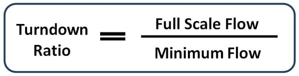
 A flow meter with a large turndown ratio will have a large operating range. This can also be indicative of the flow meter’s cost. For example, variable area flow meters (rotameters) typically have lower turndown ratios compared to thermal mass flow meters.
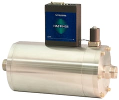 Most analog mass flow controllers also have an accuracy of ± 1% FS. However, they typically have an automatic valve shut circuit that closes the valve at flow rates below 2% of FS. This is to ensure full valve closure in the event of a small zero offset. The usable range is from 2% to 100%. Since measurement is not possible below 2%, these will have a turndown ratio of 100/2 = 50/1 or 50:1.
